Plunge Milling: Benefits, Tool Selection, and Cutting Parameters in CNC Machining
17 min
- What Is Plunge Milling?
- Common Plunge Milling Approaches
- Plunge Milling vs Conventional Milling
- Advantages and Limitations of Plunge Milling
- Plunge Milling Tools and Cutting Parameters
- Common Problems in Plunge Milling
- When Should You Use Plunge Milling?
- How Engineers Select a Plunge Milling Strategy
- Plunge Milling in CNC Machining Projects
- Conclusion About Plunge Milling
- FAQ About Plunge Milling
Key Takeaways About Plunge Milling
- Plunge milling removes material by feeding the cutter along the Z-axis rather than relying mainly on side cutting.
- The process reduces tool deflection by directing more cutting force toward the spindle axis.
- It is commonly used for deep pockets, cavities, long-reach features, and heavy roughing operations.
- Indexable plunge cutters are often used for high stock removal, while center-cutting end mills can handle smaller features.
- Plunge milling feeds and speeds depend on tool geometry, workpiece material, cutting depth, and machine rigidity.
- Poor chip evacuation can increase heat, accelerate tool wear, and reduce process stability in deep features.
- Plunge milling is primarily a roughing strategy and is usually followed by conventional milling to achieve final dimensions and surface finish.
Deep pockets, forged surfaces, and large stock allowances can complicate roughing operations. As the tool overhang increases, radial cutting forces often become a larger concern than spindle power.
Plunge milling approaches stock removal differently. The cutter moves into the workpiece at programmed locations and removes material through repeated plunging cycles. This approach is useful for deep cavities, mold bases, and parts where long side cuts may cause tool deflection.
CNC plunge milling (Image source: Wikipedia)
Tool performance depends on more than the plunge strategy itself. The cutter type, plunge distance, insert strength, machine rigidity, and chip removal method all affect the operation. A tool that works well for shallow cuts may lose stability when the reach becomes deeper, especially as tool overhang increases beyond standard cutter lengths.
This article covers plunge milling applications, cutter selection, programming considerations, cutting parameter selection, process limitations, and the differences between plunge milling and conventional milling strategies used in CNC machining.
What Is Plunge Milling?
Plunge milling for spur face-gear - Image source: ScienceDirect
Plunge milling is a CNC machining process where the cutting tool moves directly into the workpiece along the Z-axis to remove material. A plunge cut refers to the individual vertical entry made by the cutter during a plunge milling operation.
Unlike traditional milling, which mainly uses side cutting with radial tool engagement, plunge milling relies mainly on axial tool engagement, while the cutting edges at the bottom and periphery share the cutting load depending on tool design. The plunge mill tool cuts downward into the material, making it suitable for deep pockets, hard materials, and parts with limited tool reach.
How Plunge Milling Works
Plung milling and roughing (Image source: Torchmach)
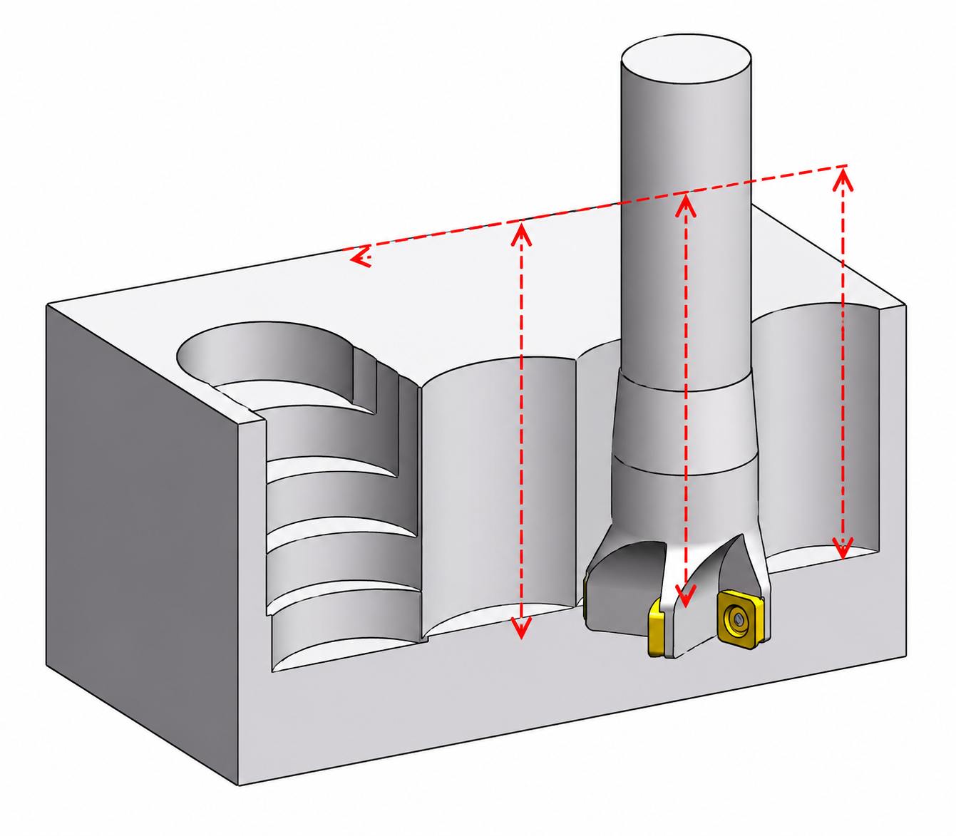
Plunge milling removes stock by feeding the cutter into the workpiece at a series of programmed locations rather than keeping the tool engaged in a long side cut. Each plunge removes a portion of the material before the cutter indexes to the next position. In most cases, plunge milling is used for roughing, with conventional milling following later to clean up walls and bring the feature to size.
Common Plunge Milling Approaches
Plunge milling strategies define how the cutter enters the workpiece and how the cutting load is controlled. Choosing the correct method helps maintain tool life, reduce vibration, and improve machining stability.
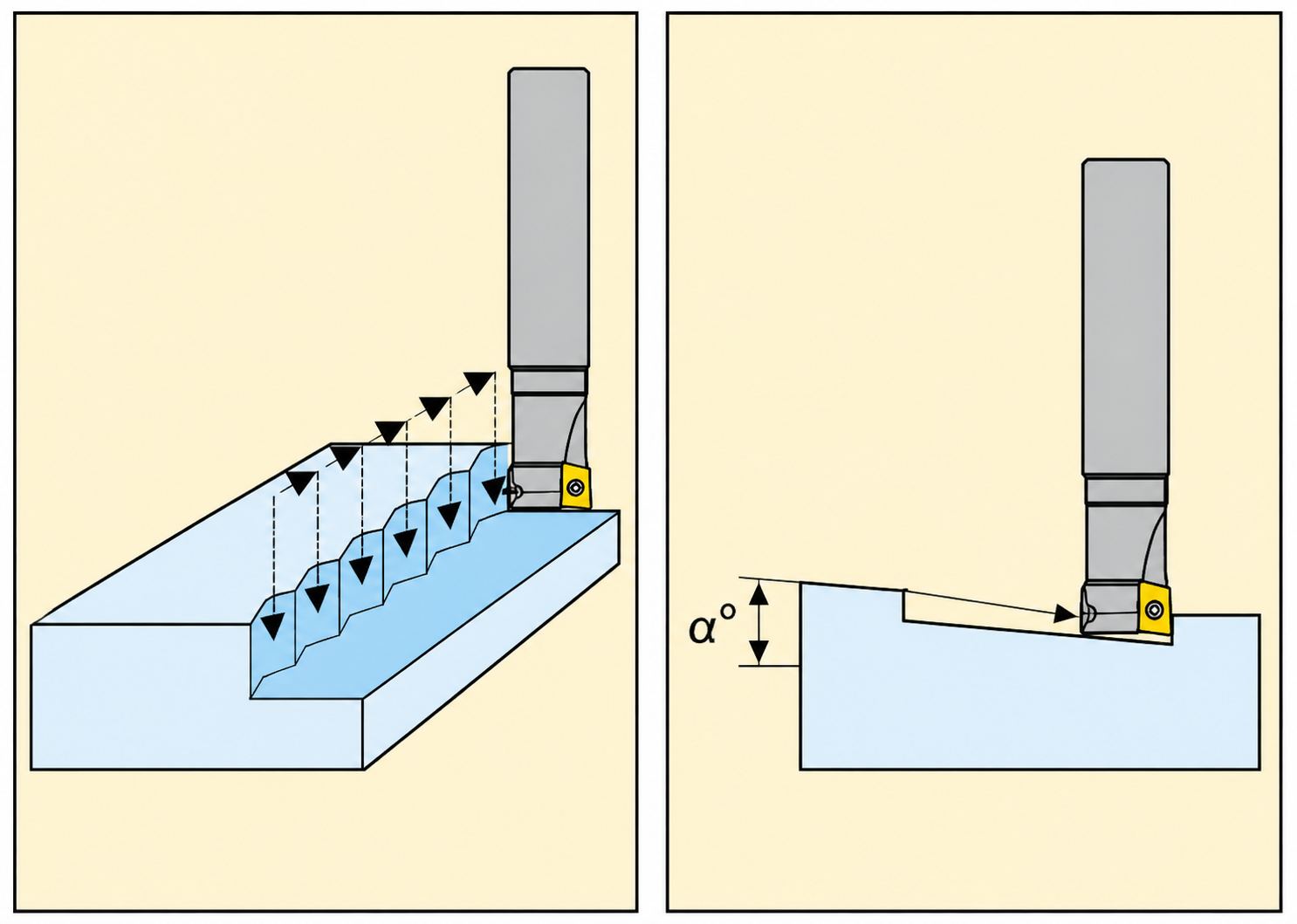
Straight Plunging
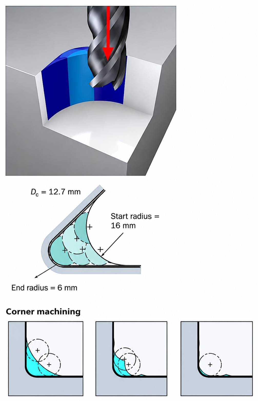
Straight plunging feeds the cutter vertically into the material without side movement. The tool removes material mainly through its end cutting edges, which reduces radial pressure on the cutter. It is commonly selected for deep cavities where a long side-cutting tool path may cause deflection.
Helical Plunging
Helical plunging uses a circular tool path while the cutter moves downward into the part. The tool gradually increases cutting engagement instead of taking a full-depth entry cut. This reduces impact on the cutting edges and helps control chip load during pocket and cavity machining.
Ramp Plunging
Ramp plunging enters the material at a controlled angle rather than moving straight down. The angled approach lowers the initial cutting force and allows the tool to engage the material more smoothly. It is useful when direct plunging would create excessive load on the cutter.
Zig-Zag Plunge Strategies
Zig-zag plunge strategies divide material removal into repeated cutting movements. The tool moves between programmed positions to remove stock in smaller sections. This helps maintain a consistent cutting load during rough machining operations.
Plunge Milling vs Conventional Milling
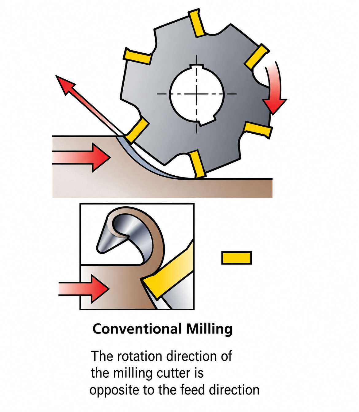
Conventional milling (Image source: Meetyou Carbide)
Plunge milling and conventional milling remove material in different ways. The main difference is how the cutting tool contacts the workpiece. Conventional milling uses the side of the cutter, while plunge milling relies more on the tool’s end cutting edges.
This difference changes the cutting force, tool behavior, and suitable applications. Plunge milling is mainly chosen when deep cuts, long tool reach, or heavy stock removal create problems for standard milling.
| Factors | Plunge Milling | Conventional Milling |
|---|---|---|
| Cutting force | Force is directed mainly toward the spindle | Force pushes the tool sideways |
| Tool movement | The tool moves into the part along the Z-axis | The tool moves across the workpiece surface |
| Tool deflection | Lower risk during deep cuts | Higher risk with long tool overhang |
| Material removal | Removes stock through repeated plunging | Removes stock through side engagement |
| Rough machining | Suitable for heavy material removal | Better for general machining operations |
| Tool wear | More controlled under stable conditions | Can increase with high radial loads |
| Surface finish | Usually needs a finishing pass | Can achieve a better finish in contour cuts |
Cutting Force Direction
During plunge milling, the cutting force acts closer to the tool centerline. This reduces the bending force applied to the cutter and helps maintain stability during deep machining.
In conventional milling, the cutter works mainly from the side. The radial force can push the tool away from the cutting path, which may cause vibration or size variation when the setup is less rigid.
Material Removal Strategy
Plunge milling removes material by making controlled vertical cuts. Instead of moving the tool sideways through a large engagement area, it removes stock in smaller sections.
Conventional milling uses the cutting edge along the tool diameter to remove material. It is effective for open surfaces, profiles, and general machining work where tool access is not limited.
Tool Life and Process Stability
Plunge milling can reduce tool stress in operations where side cutting becomes unstable. Lower radial loading helps reduce chatter and improve cutting consistency.
Conventional milling can provide good tool life in normal conditions. However, deep cuts, long tool extensions, and hard materials can increase cutting pressure and accelerate wear.
Surface Finish and Accuracy
Plunge milling is mainly used for roughing because it prioritizes stability and material removal. A separate finishing operation is usually required to achieve final surface requirements.
Conventional milling is commonly used for finishing because the tool follows the part profile more directly. With proper setup, it can produce better surface finish and dimensional control.
In practice, the choice between plunge milling and conventional milling depends on the feature geometry and how the cutter reaches the cutting area. Deep cavities and long tool overhangs often require a different roughing strategy than open features. For prototype and low-volume CNC parts, JLCCNC reviews customer CAD models before production to evaluate machining feasibility and process selection.

Precision CNC Machining Service
Professional manufacturing, fast turnaround, and quality assurance.
Advantages and Limitations of Plunge Milling
Plunge milling is mainly selected when standard milling creates high side forces, tool deflection, and vibration problems. It provides better control during heavy roughing, but it also has limits in finishing and complex tool movements.
Advantages of Plunge Milling
- Reduces radial cutting pressure on the tool during heavy cuts
- Helps control tool deflection when using long tool extensions
- Provides stable cutting conditions in deep pockets and cavities
- Allows higher material removal when side milling becomes unstable
- Reduces vibration caused by excessive tool bending
- Improves machining control on hard-to-reach features
- Can extend tool life by reducing uneven side loading
Limitations of Plunge Milling
- Not suitable for producing complex surface profiles
- Usually requires a separate finishing operation after roughing
- Limited to tools designed for axial cutting loads
- Requires proper chip removal, especially in deep cuts
- Cannot replace conventional milling for all part features
- Tool path planning can be more complex for large areas
- Surface quality may not match side milling operations
When Conventional Milling Is a Better Choice
- Conventional milling is preferred when the final surface finish and part accuracy are important. It gives better control over finished walls and profiles.
- It works well for curved surfaces, contours, and complex features that need smooth tool movement.
- For shallow cuts and open areas, conventional milling can remove material quickly with less tool stress.
- Facing, slotting, and profile milling are common operations where conventional milling is widely used.
- When the cutter can reach the feature without a long extension, conventional milling can provide better cutting performance.
- Some parts can be rough machined and finished with conventional milling in the same setup, reducing extra operations.
Plunge Milling Tools and Cutting Parameters
Plunge milling requires suitable tools and cutting conditions to handle axial cutting forces. Tool type, geometry, cutting speed, feed rate, and machine condition all affect machining stability and tool performance.
Indexable Cutters vs End Mills
End mill plunge cuts are commonly used when pocket geometry limits the use of larger plunge cutters. An end mill plunge cut requires a center-cutting end mill because the tool must remove material at the center of the cutter during vertical entry.
Indexable plunge cutters use replaceable inserts and are commonly used for heavy material removal. They are suitable for roughing because they handle higher cutting loads and reduce tooling costs.
Solid carbide end mills are often selected for smaller features, deeper cavities, or applications where cutter access limits the use of larger indexable tools. They provide better accuracy and can handle detailed machining areas where larger cutters cannot reach.
Tool Geometry Considerations
Tool geometry affects cutting force, chip flow, and tool life. A cutter with proper end cutting edges is required because plunge milling relies on axial engagement.
Important factors include:
- Number of cutting edges
- Helix angle
- Tool diameter
- Corner strength
- Insert geometry
A rigid tool with suitable edge geometry helps reduce vibration and maintain stable cutting.
Plunge Milling Feeds and Speeds
Plunge milling parameters depend on the tool and workpiece materials, as well as the cutting depth.
Key factors include:
- Cutting speed based on material hardness
- Feed rate based on chip load per tooth
- Depth of plunge cut
- Tool diameter and cutting edge count
- Coolant requirements
Incorrect settings can cause tool wear, poor chip removal, or unstable cutting.
Typical Starting Cutting Data Range (General Reference)
Actual parameters depend on cutter manufacturer recommendations, tool diameter, machine rigidity, and coolant conditions.
| Material | Cutting Speed (m/min) | Feed per Tooth (mm/tooth) |
|---|---|---|
| Aluminum | 150–400 | 0.05–0.20 |
| Carbon Steel | 80–180 | 0.05–0.15 |
| Stainless Steel | 50–120 | 0.04–0.12 |
| Cast Iron | 100–250 | 0.08–0.20 |
Machine Rigidity and Power Requirements
Plunge milling shifts a larger portion of the cutting load into the spindle axis, which increases the importance of spindle rigidity and toolholding stability. A rigid machine setup helps maintain accuracy and prevents vibration.
The machine should have:
- Strong spindle support
- Stable workholding
- Proper tool holding system
- Enough spindle power for the cutter size
A weak setup can limit cutting depth and reduce tool performance.
Common Problems in Plunge Milling
Plunge milling problems usually appear during roughing when the cutter, tool path, and cutting data do not match the job. Because the tool enters the material vertically, chip space, edge strength, and machine rigidity become important factors.
Poor Chip Evacuation
Deep plunge cuts can trap chips at the bottom of the pocket. The cutter may pass through the same chips again, causing extra heat and cutting-edge damage.
For deep features, machinists usually adjust plunge depth, coolant direction, and tool selection to give chips enough space to leave the cutting area.
Excessive Tool Wear
The bottom edges of the cutter handle the impact during each plunge. If the material is hard or the cutting load is too high, these edges wear faster than the side flutes.
Using the correct insert grade, reducing aggressive plunge depth, and matching the tool to the material are key to controlling wear.
Chatter and Vibration
Plunge milling can still produce vibration when the setup is not rigid enough. Long tool extensions, weak holders, or heavy cutting loads can cause unstable cutting.
A shorter tool length, stronger clamping, and suitable cutting parameters help keep the cutter stable during the operation.
Inefficient Toolpaths
A poor plunge strategy can waste machining time and overload the cutter. Too many entry points increase cycle time, while large step-downs can put unnecessary stress on the tool.
Good programming focuses on reducing unnecessary movements and keeping the cutter engaged within its working range.
When Should You Use Plunge Milling?
Plunge milling is not used for every CNC operation. It is mainly chosen when side cutting creates problems with tool deflection, vibration, or cutting load. It helps remove material in areas where maintaining tool stability is difficult.
Deep Cavities and Pockets
Plunge milling is useful when machining deep pockets where the cutter has a large overhang. Instead of forcing the tool sideways through the material, the cutter removes stock through vertical movements, reducing bending during roughing.
Long-Reach and High Aspect-Ratio Features
Long tools are more likely to bend when used for normal milling cuts. Plunge milling reduces the side force on these tools, making it a better option for reaching deep features while keeping the cutting action stable.
Difficult-to-Machine Materials
Materials such as hardened steels, titanium, and nickel alloys can create high cutting loads during machining. Plunge milling helps control these loads by reducing radial pressure on the tool.
In nickel-based alloys and titanium, radial cutting forces often increase rapidly as engagement grows. Plunge milling helps control these loads by directing more force toward the spindle axis. This can improve tool stability when machining deep cavities or forged stock with uneven surfaces.
Heavy Roughing Operations
For large stock removal, plunge milling can provide a more stable roughing method. It is often used to remove excess material before finishing passes, especially when aggressive side milling causes chatter or tool wear.
How Engineers Select a Plunge Milling Strategy
Plunge milling is chosen based on the machining problem, not just the part feature. Engineers usually compare the cutting method, tool behavior, machine limits, and production targets before deciding if plunge milling is the right approach.
Geometry and Feature Accessibility
Part geometry plays a major role in selecting plunge milling. Deep pockets, narrow sections, and features with limited cutter access can make normal side milling difficult because the tool may deflect under radial cutting forces.
Engineers check the cavity depth, required tool length, corner access, and remaining stock before selecting a plunge approach.
Material and Machine Constraints
The workpiece material and machine capability determine how aggressive the plunge operation can be. Hard materials increase cutting pressure, while low spindle power or weak setups can limit tool performance.
Tool diameter, cutter type, spindle power, holder rigidity, and fixture strength are reviewed before setting cutting conditions.
Productivity and Cost Considerations
Plunge milling can reduce roughing time when a large amount of material needs to be removed from deep features. It can also reduce the need for oversized tools or unstable long-reach cuts.
However, engineers also consider tooling cost, programming time, and whether a finishing operation is still required after roughing. The best strategy is the one that reduces total machining effort while meeting part requirements.
Plunge Milling in CNC Machining Projects
Plunge milling is usually used as a roughing method inside a complete CNC process. Engineers apply it when removing stock, as normal side milling would create excessive tool load, deflection, or unstable cutting conditions.
The process is often followed by finishing operations such as contour milling, pocket milling, finishing, or wall cleanup to achieve final dimensions and surface requirements.
Prototype and Low-Volume Production
For CNC rapid prototyping and low-volume parts, plunge milling can reduce setup complexity when machining deep features. Instead of selecting a long end mill for full-depth side cutting, engineers may use a shorter, stronger cutter to remove the majority of the material.
This approach is useful when the part has deep cavities, limited tool access, or changing designs where dedicated tooling is not practical. The remaining stock is then removed during finishing passes.
For CNC prototype and low-volume production, selecting the right roughing strategy can significantly affect machining cost and lead time. JLCCNC helps engineers manufacture CNC parts by reviewing CAD models and recommending suitable machining approaches.
High-Material-Removal Applications
Plunge milling is considered when roughing requires large stock removal and tool deflection becomes a limiting factor. The axial cutting direction allows the cutter to take deeper steps without creating the same side load as conventional milling.
Engineers typically evaluate factors such as material hardness, cavity depth, cutter diameter, spindle power, and required roughing allowance before selecting plunge milling.
Combining Plunge Milling and Conventional Milling
In many CNC programs, plunge milling and conventional milling are used together rather than as alternatives. Plunge milling removes bulk material from deep areas, while conventional milling completes the final shape.
For example, a deep pocket may be plunge roughed to leave 0.5–1 mm stock on the walls, followed by contour milling to achieve the required tolerance and surface finish. This combination helps balance machining time, tool life, and part accuracy.
Conclusion About Plunge Milling
Plunge milling is a useful CNC machining method for removing material from deep features, difficult areas, and heavy roughing operations. Its main advantage comes from the way cutting forces act along the tool axis, which reduces the side pressure seen in standard milling.
The process is not a replacement for conventional milling. Instead, engineers often combine both methods, using plunge milling for bulk material removal and conventional milling for final profiles and surface requirements.
For parts that involve deep pockets, long tool reach, or challenging materials, selecting the right plunge strategy and validating cutter behavior early in the process can prevent many of the stability problems that appear during roughing.
When evaluating a part for CNC machining, features such as cavity depth, tool access, and workholding conditions often determine whether plunge milling is the better option. JLCCNC works with customer drawings and CAD models to review machining approaches before production begins.
Upload your CAD file to get a fast quote starting from $1, with lead times as short as 3 days.
Precision CNC Machining Service
Professional manufacturing, fast turnaround, and quality assurance.
FAQ About Plunge Milling
Q: What is plunge milling?
Plunge milling is a CNC cutting method where the tool moves straight into the workpiece along the Z-axis.The cutter removes material primarily through axial engagement rather than side cutting.
Q: What is a plunge cut?
A plunge cut is when a rotating tool enters the material vertically. The tool moves downward to create depth before moving to the next cutting position.
Q: Can an end mill be used for plunge milling?
Some end mills can be used for plunge milling if they have center-cutting capability. Standard non-center-cutting end mills are not suitable because they cannot cut effectively at the tool center.
Q: What tools are used for plunge milling?
Common tools include indexable plunge cutters and solid carbide end mills with strong bottom cutting edges. The tool choice depends on the material, cutting depth, and amount of stock to remove.
Q: How do feeds and speeds differ in plunge milling?
Plunge milling usually requires different cutting data than side milling because the cutting load acts on the tool end. Feed rate, spindle speed, and plunge depth are adjusted based on cutter size, material, and machine power.
Q: When is plunge milling better than conventional milling?
Plunge milling is often selected for deep cavities, long tool extensions, and heavy roughing, where side milling may cause too much tool bending or vibration.
Q: Is plunge milling suitable for finishing operations?
It is mainly used for roughing. The process removes material efficiently but usually does not produce the surface finish needed for final part requirements.
Q: What is the difference between plunge milling and plunge grinding?
Plunge milling uses a cutting tool with sharp edges to remove material as chips. Plunge grinding uses an abrasive wheel and is mainly used for precision finishing and surface correction.
Popular Articles
• Cutting with Precision: A Comprehensive Guide to CNC Water Jet Technology
• CNC Coolant Explained: Types, Maintenance & Safety
• Rake Angle in Machining: Machinists’ Guide to Perfect Cuts
• What Steps Are Taken To Minimize Waste In CNC Machining Processes?
• How EDM Wire Cutting Works: Complete Guide to Precision CNC Wire Cutting
Keep Learning
Chatter in Machining: Causes, Effects, and How to Reduce It
CNC milling operation producing visible chatter marks on an aluminum workpiece Quick Chatter Diagnosis Checklist Symptom Most Likely Cause First Action High-pitched squeal Regenerative chatter Change spindle speed ±15% Chatter only in deep pockets Excessive tool overhang Shorten tool Chatter on thin walls Low workpiece rigidity Improve fixturing Chatter after tool replacement Runout / holder issue Check tool holder Chatter only during finishing DOC too small / rubbing Increase feed or adjust speed It ......
What Is Tool Offset in CNC? Types, Setup & Best Practices
CNC tool offset setup with measurement overlay Key Takeaways CNC offsets connect programmed intent with actual cutter position. Length data guides Z-axis depth control. Radius data protects part size during contour milling. Geometry values define the cutter's measured baseline. Wear values support fine correction during production. Verified data lowers scrap risk before full machining. Good offset habits protect tools, fixtures, and parts. In the context of CNC machining , tool offset is the quiet set......
Trochoidal Milling: Complete Guide to High-Efficiency CNC Machining
Key Takeaways Trochoidal milling combines circular cutter motion with continuous forward feed. The cutter normally engages 5 to 20% of its diameter instead of making a full-width cut. A smaller engagement angle limits force changes during slotting and pocket roughing. Low radial engagement often allows greater axial depths of cut than conventional slot milling. CAM software calculates the circular path automatically from the selected machining parameters. This strategy is widely applied to titanium, s......
What Is Die Casting? Process, Materials, and Applications
Key Takeaways Die casting is a metal casting process that forces molten metal into a reusable steel mold under high pressure, producing parts with tight tolerances and good surface finish at high volume. Aluminum die casting is the most common form by far, thanks to its combination of light weight, decent strength, and good corrosion resistance. The die casting process runs through mold preparation, injection, cooling, and ejection in a cycle that can repeat every few seconds to minutes depending on p......
First Angle vs Third Angle: Understanding Orthographic Projection Methods
Key Takeaways Orthographic projection is the system that lets a 3D part be represented through multiple 2D views, front, top, side, and so on. First angle projection and third angle projection are the two standard methods for arranging those views, and they place views in opposite positions relative to the object. First angle projection is the ISO standard used across most of Europe, India, China, Russia, and many other countries following ISO standards Third angle projection is the standard in the Un......
Micro EDM Machining: Capabilities, Materials, and Applications for Precision Components
Key Takeaways About Micro EDM Machining Only electrically conductive materials can be machined. Hole diameters can reach below 50 μm on specialized equipment. The process produces almost no mechanical cutting force, making it suitable for thin or delicate features. Surface integrity still requires attention because recast layers and heat-affected zones may remain after machining. Micro EDM is often combined with CNC machining, with milling producing the main geometry before EDM finishes critical micro......