CNC G Code List: Functions and Common Uses
22 min
- CNC G Code List and Their Functions
- How Do Modal and Non-Modal G Codes Work?
- Example of G Codes in a CNC Program
- How to Verify G Code Compatibility Before Running a CNC Program
- FAQs About CNC G Codes
Key Takeaways
- G codes control CNC motion modes and machining functions, including rapid positioning, linear and circular interpolation, canned cycles, coordinate selection, and tool compensation. Feed rate values are typically specified with the F address, while G codes such as G94 and G95 select how the feed rate is interpreted.
- Modal G codes stay active once programmed until cancelled by another code in the same group. Non-modal G codes apply only to the block where they appear.
- Codes such as G00, G01, and G02 have broadly consistent motion functions across common CNC controls. Coordinate modes and canned cycles require closer attention because their definitions can differ between milling and turning systems.
- Always verify G codes against the specific machine and controller documentation before running a program.
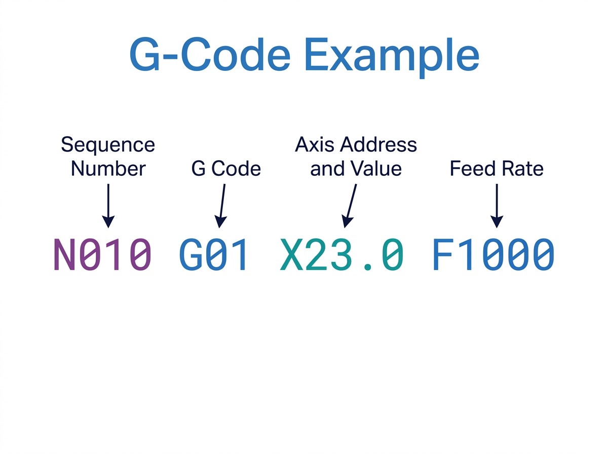
Example of sequence number, G code, X-axis address and value, and feed rate
G codes are commands in CNC programs that specify motion modes and machining functions. Depending on the code and controller, they can control rapid positioning, linear or circular interpolation, canned cycles, coordinate modes, and tool compensation.
Even when CAM software generates the program, engineers and operators still need to inspect the output for unexpected motion or post-processor errors before machining begins.
For an overview of how G codes and M codes work together in CNC programming, see the G and M codes guide.
CNC G Code List and Their Functions
This CNC G code list brings commonly used commands and selected machine-specific codes into one numerical reference table. When a code has different meanings on milling and turning machines, the table lists those uses separately and identifies the relevant controller or machine type.
The descriptions cover common programming conventions rather than a universal code standard. Modal group assignments, address formats, cycle parameters, and execution behavior can vary by controller. Check the programming manual for the target machine before using a code in a production program.
Note
This is a reference for commonly used G codes and selected controller-specific examples, not an exhaustive list of every code supported by every CNC machine. Codes that share a number may have different functions across machine types or control families. Verify the exact definition, syntax, prerequisites, and cancellation behavior in the target machine's programming manual before running a program.
| G Code | Function | Controller / Machine | Notes |
|---|---|---|---|
| G00 | Rapid positioning | Common on many CNC controls | Moves axes to a programmed position at rapid traverse rates. The resulting path may not be a straight line, so check clearance before using rapid motion near the workpiece. |
| G01 | Linear interpolation | Common on many CNC controls | Moves along a straight-line path at the programmed feed rate. The F value and feed interpretation depend on the active feed mode. |
| G02 | Clockwise circular interpolation | Common on many CNC controls | Produces a clockwise arc in the selected plane. Arc definition commonly uses I/J/K center offsets or an R value, depending on the control and programming format. |
| G03 | Counterclockwise circular interpolation | Common on many CNC controls | Produces a counterclockwise arc in the selected plane. The active plane determines which axes define the arc. |
| G04 | Dwell | Common on many CNC controls | Pauses execution for a specified time. The dwell address and time units depend on the controller. |
| G05 | Controller-specific high-speed or precision machining function | Selected controllers | G05 has different definitions across controller families. Check the target control's programming manual for its exact function and supported syntax before use. |
| G05.1 | Advanced preview control | Selected FANUC controls | Used for specific high-speed machining functions on supported FANUC controls. The required syntax and options depend on the control series. |
| G09 | Exact stop check | Selected controllers | Requires the machine to reach the programmed position before continuing. This is generally a one-block command; confirm implementation on the target control. |
| G10 | Programmable data input | Selected controllers | Can write work offsets or other CNC data through program commands. Address formats and supported data types are controller-specific. |
| G12 | Clockwise circular pocket milling | Selected Haas controls | Used for a circular pocket-milling cycle on supported controls. Do not treat it as a universal G code. |
| G12.1 | Polar coordinate interpolation | Selected turning controls | Enables polar interpolation on supported turning systems. It is distinct from the G12 circular pocket cycle used on some milling controls. |
| G13 | Counterclockwise circular pocket milling | Selected Haas controls | Used for a counterclockwise circular pocket-milling cycle on supported controls. |
| G15 | Cancel polar coordinate mode | Selected FANUC controls | Cancels the polar coordinate mode established by the corresponding supported command. Confirm the control-specific syntax. |
| G16 | Polar coordinate mode | Selected FANUC controls | Allows positions to be programmed using polar coordinates on supported controls. Availability and address conventions vary. |
| G17 | XY plane selection | Common on many milling controls | Selects the XY plane for applicable arc and cycle operations. |
| G18 | XZ plane selection | Common on many CNC controls | Selects the XZ plane for applicable arc and cycle operations. It is commonly used for turning operations. |
| G19 | YZ plane selection | Common on many milling controls | Selects the YZ plane for applicable arc and cycle operations. |
| G20 | Inch input | Common on many CNC controls | Interprets applicable programmed linear values in inches. Confirm the expected units before running the program. |
| G21 | Metric input | Common on many CNC controls | Interprets applicable programmed linear values in millimeters. |
| G27 | Reference position return check | Selected controllers | Checks whether the machine reaches its reference position as specified by the control. Exact behavior and supported axes vary. |
| G28 | Return to reference position | Common on many CNC controls | Returns an axis to a machine reference position, often through an intermediate point. Review the programmed path and the controller's reference-return behavior before execution. |
| G29 | Return from reference position | Selected controllers | Used on supported controls to move from a reference-return position toward a programmed point, often using a point associated with G28. Exact behavior varies. |
| G30 | Return to a secondary reference position | Selected controllers | Moves to a second or other configured reference position where supported. The available positions and selection method depend on the control. |
| G31 | Skip-function move | Selected controllers | Executes a move that can stop when a skip signal is received. Used in supported probing or measurement routines; signal handling and syntax are control-specific. |
| G32 | Thread cutting | CNC turning controls | Produces a spindle-synchronized threading move on supported turning controls. It is typically used for single-pass threading rather than a complete multi-pass cycle. |
| G40 | Cancel cutter or tool-nose-radius compensation | Milling and turning controls | Cancels the applicable compensation mode. The required cancellation move and safe lead-out depend on the control and operation. |
| G41 | Cutter radius compensation left | Milling controls | Offsets the tool path to the left of the programmed contour when viewed in the direction of travel. The controller must have a valid cutter-radius offset, and the lead-in move must provide sufficient distance to establish compensation. |
| G41 | Tool-nose-radius compensation left | Turning controls | Applies the supported left-side tool-nose-radius compensation. The insert orientation and programmed contour affect the result. |
| G42 | Cutter radius compensation right | Milling controls | Offsets the tool path to the right of the programmed contour when viewed in the direction of travel. The controller must have a valid cutter-radius offset, and the lead-in move must provide sufficient distance to establish compensation. |
| G42 | Tool-nose-radius compensation right | Turning controls | Applies the supported right-side tool-nose-radius compensation for turning operations. |
| G43 | Positive tool length compensation | Selected milling controls | Applies the tool length offset, commonly selected with an H address. Confirm the control's compensation direction and activation requirements. |
| G43.1 | Dynamic tool length compensation | Selected controls | Supports a form of dynamic tool length compensation on certain controls. The exact function and syntax are controller-specific. |
| G43.2 | Additional tool length compensation | Selected controls | Supports an additional tool length offset on certain controls. Confirm whether the control and machine configuration support it. |
| G43.4 | Tool center point control | Selected multi-axis controls | Used for tool center point control on supported machines. Activation requirements and behavior depend on the control and machine configuration. |
| G43.5 | Tool center point control (selected FANUC controls) | Selected controls | Used for tool center point control on supported FANUC configurations. Confirm the control series, required options, and programming syntax in the applicable manual. |
| G44 | Negative tool length compensation | Selected controls | Applies negative tool length compensation where supported. It is not used in the same way on every controller. |
| G49 | Cancel tool length compensation | Selected milling controls | Cancels the active tool length compensation mode. Confirm the safe sequence for retracting and changing tools on the target machine. |
| G50 | Set maximum spindle speed | Selected turning controls | Often sets the upper spindle-speed limit used with constant surface speed. The address and behavior depend on the turning control. |
| G50 | Scaling cancellation or coordinate-related function | Selected milling controls | Some controls assign G50 a different function. Do not transfer the turning definition to a milling machine without checking its manual. |
| G51 | Scaling | Selected controllers | Applies coordinate scaling on controls that support it. Scaling factors, center points, and cancellation behavior vary. |
| G52 | Local coordinate offset | Selected controllers | Applies a local coordinate shift where supported. Do not assume that a fixed cancellation block works on every control; verify the offset behavior and reset method. |
| G53 | Machine coordinate move | Selected controllers | Executes a move in machine coordinates on supported controls. On many common controls, G53 applies only to the block in which it appears. Check the required motion command and any restrictions in the target controller's manual. |
| G54 | Work coordinate system 1 | Common on many CNC controls | Selects the first standard work offset. Its stored origin determines the relationship between programmed coordinates and the workpiece. |
| G55 | Work coordinate system 2 | Common on many CNC controls | Selects the second standard work offset. |
| G56 | Work coordinate system 3 | Common on many CNC controls | Selects the third standard work offset. |
| G57 | Work coordinate system 4 | Common on many CNC controls | Selects the fourth standard work offset. |
| G58 | Work coordinate system 5 | Common on many CNC controls | Selects the fifth standard work offset. |
| G59 | Work coordinate system 6 | Common on many CNC controls | Selects the sixth standard work offset. Some controls support additional work offsets through extended syntax. |
| G54.1 | Extended work coordinate systems | Selected FANUC and compatible controls | Selects an extended work offset using controller-specific syntax, often with a P address. The number of available offsets depends on the control. |
| G61 | Exact stop mode | Selected controllers | Selects exact-stop path control where supported. This can affect corner behavior and machining time. |
| G64 | Continuous-path mode | Selected controllers | Selects a continuous-path or blending mode on supported controls. The controller may smooth transitions to maintain motion, subject to its settings. |
| G68 | Coordinate rotation | Selected milling controls | Rotates the programmed coordinate system on supported controls. The rotation center, angle format, and cancellation method vary. |
| G68.2 | Tilted working plane | Selected multi-axis controls | Defines a tilted working plane on supported controls. The required angles and subsequent coordinate behavior are controller-specific. |
| G69 | Cancel coordinate rotation | Selected controllers | Cancels a coordinate rotation mode where supported. Confirm whether other coordinate transformations remain active. |
| G70 | Finishing cycle | FANUC turning controls | Executes a finishing cycle over a previously defined contour on supported FANUC turning controls. The contour format and cycle parameters depend on the control series. |
| G71 | Rough turning cycle | FANUC turning controls | Executes a rough-turning cycle using a defined contour and control-specific parameters. The block format differs by control series. |
| G72 | Rough facing cycle | FANUC turning controls | Executes a rough-facing cycle on supported turning controls. |
| G73 | Pattern-repeating cycle | Selected turning controls | Repeats a previously defined contour under the cycle's programmed conditions. The exact syntax depends on the control. |
| G73 | High-speed peck drilling cycle | Selected milling controls | Performs a peck-drilling cycle with a short retract or chip-break motion on supported controls. Its retract behavior differs from G83. |
| G74 | Face-grooving or pecking cycle | Selected turning controls | Used for supported turning operations such as face grooving or pecking. The cycle definition depends on the controller. |
| G74 | Left-hand tapping cycle | Selected milling controls | Used for left-hand tapping on certain milling controls. Confirm spindle direction, tapping synchronization, and cycle syntax. |
| G75 | OD/ID grooving cycle | Selected turning controls | Executes a grooving cycle on supported turning controls. The cycle typically uses repeated cutting moves; parameter formats vary. |
| G76 | Multi-pass threading cycle | CNC turning controls | Automates multiple threading passes on supported turning controls. Threading parameters and block formats depend on the control. |
| G76 | Fine boring cycle | Selected milling controls | Performs a fine-boring cycle on controls that assign this function to G76. Spindle orientation and retract behavior depend on the machine. |
| G80 | Cancel canned cycle | Common on many milling controls | Cancels an active canned cycle where supported. Use it before subsequent motion that should not repeat the drilling or boring cycle. |
| G81 | Drilling cycle | Common on many milling controls | Feeds to the programmed drilling depth and retracts according to the active cycle parameters. |
| G82 | Drilling cycle with dwell | Selected milling controls | Adds a dwell at the bottom of the hole on supported controls. It is often used for spot drilling or operations requiring a dwell; it is not universally a counterboring cycle. |
| G83 | Peck drilling cycle | Common on many milling controls | Drills in increments with retracts for chip clearance. The retract method and peck parameters depend on the control. |
| G84 | Tapping cycle | Common on many milling controls | Performs a tapping cycle on supported controls. Rigid-tapping requirements, spindle synchronization, and return behavior must be checked. |
| G85 | Boring cycle, feed in and feed out | Selected milling controls | Feeds into the bore and retracts at a programmed feed rate. Do not treat it as a universal reaming cycle. |
| G86 | Boring cycle with spindle stop | Selected milling controls | Stops the spindle at the programmed depth before retracting on supported controls. Confirm the retract method for the target machine. |
| G87 | Back-boring cycle | Selected milling controls | Supports back-boring operations on controls that implement the cycle. Tool orientation and shifting requirements depend on the machine. |
| G88 | Boring cycle with manual retract | Selected milling controls | Uses a manual-retract sequence on supported controls. Operator interaction and spindle behavior depend on the control. |
| G89 | Boring cycle with dwell | Selected milling controls | Adds a dwell at the programmed depth before feed retract on supported controls. |
| G90 | Absolute coordinate mode | Common on many milling controls | Interprets programmed positions relative to the active coordinate origin. On some turning controls, G90 instead identifies a turning cycle. |
| G90 | Turning cycle | Selected turning controls | Defines a turning cycle on some controls. Do not assume it means absolute positioning on every lathe. |
| G91 | Incremental coordinate mode | Common on many milling controls | Interprets programmed positions as increments from the current position. Confirm how the controller handles each axis and any mixed absolute/incremental address formats. |
| G93 | Inverse-time feed mode | Selected controllers | Uses inverse-time feed programming. The F value represents an inverse-time feed specification according to the controller's rules; it should not be described universally as "blocks per minute." |
| G94 | Feed per minute | Common on many milling controls | Interprets the programmed feed rate as distance per minute, such as mm/min or in/min. |
| G95 | Feed per revolution | Selected controls | Interprets feed as distance per spindle revolution where supported. Check the control's feed-mode assignments, especially on turning centers. |
| G96 | Constant surface speed | CNC turning controls | Adjusts spindle speed to maintain the programmed surface speed as the workpiece diameter changes. Set an appropriate maximum RPM limit where required by the control. |
| G97 | Cancel constant surface speed / fixed-RPM mode | Selected turning controls | On supported turning controls, G97 cancels constant surface speed and returns spindle-speed programming to RPM mode. Do not assume that G97 is supported or has the same meaning on a milling controller. |
| G98 | Initial-plane return for canned cycles | Selected milling controls | Returns to the initial Z plane after a canned cycle on controls using this convention. |
| G98 | Feed per minute | Selected turning controls | Some turning controls use G98 to select feed per minute. Verify the control-specific definition rather than applying the milling meaning. |
| G99 | R-plane return for canned cycles | Selected milling controls | Returns to the R plane after a canned cycle on controls using this convention. |
| G99 | Feed per revolution | Selected turning controls | Some turning controls use G99 to select feed per revolution. Its meaning differs from the milling canned-cycle return mode. |
How Do Modal and Non-Modal G Codes Work?
Modal G codes are the most important concept to understand when reading or writing CNC programs. A modal G code stays active after the block where it's programmed. It continues to apply to every subsequent block until a code from the same modal group replaces or cancels it. The CNC controller does not need the code repeated in every block because the mode remains active until it is replaced or cancelled.
Take G01 as an example. Once you program G01 in a block, every subsequent motion block executes as a linear feed move, even if G01 isn't written again. The mode is active until G00, G02, G03, or another Group 1 code appears. This allows consecutive cutting blocks to omit the motion code when the same mode remains active. The controller continues to apply the previously established G01 mode until another code in the same modal group replaces it.
Non-modal G codes apply to the block in which they are programmed rather than remaining active across subsequent blocks. G04 (dwell), for example, pauses execution for the specified time and does not carry the dwell into the next block. G28 and G53 also operate as single-block commands on many common controls, although their exact behavior must be checked against the target controller's documentation.
A program should not rely on the controller's previous modal state. If a program assumes G90 is active but the controller is still in G91, programmed positions may be interpreted incrementally rather than from the active coordinate origin. The resulting motion can differ substantially from the intended toolpath. Explicitly establish the required modes at the start of the program, following the machine builder's programming conventions.
This is why experienced programmers include a safety initialization block at the beginning of every program:
N010 G21 G17 G40 G49 G80 G90 G94
On many milling controls, this block establishes the metric unit system, XY plane, cancelled cutter and tool length compensation, cancelled canned cycle, absolute positioning, and feed-per-minute mode. Adapt the initialization block to the target controller and machine, and explicitly set any additional modes required by the operation.
Modal groups also matter for post-processor configuration. The group assignment for a specific G code determines which other codes it cancels. Modal group assignments determine which active modes are replaced when a new G code is programmed. Do not assume that a code belongs to the same group across different controller families; check the programming manual when configuring a post-processor or troubleshooting unexpected modal behavior.
Example of G Codes in a CNC Program
The following FANUC-style example illustrates a rectangular contour-milling pass on a vertical machining center. It demonstrates coordinate modes, tool length compensation, cutter radius compensation, and a reference return. It does not clear the interior of a pocket. The code is illustrative; verify the syntax, offsets, toolpath, and safe clearances for the target machine and controller before running it.
O3001                              ; Program number
N010 G21 G17 G40 G49 G80 G90 G94
                                   ; Metric units, XY plane, cancel compensation
                                   ; and canned cycles, absolute mode, feed per minute
N020 G28 G91 Z0                    ; Return Z to the machine reference position
N030 G90 G54                       ; Restore absolute mode and select work offset G54
N040 T01 M06                       ; Tool change: tool 1
N050 S5000 M03                     ; Set spindle speed to 5000 RPM and start clockwise
N060 G00 G43 H01 Z50.0             ; Apply tool length offset H01 and move to Z50
N070 G00 X10.0 Y10.0               ; Rapid to the programmed XY position
N080 G00 Z2.0                      ; Rapid to the approach plane
N090 G01 Z-5.0 F200                ; Feed to the programmed depth
N100 G01 G41 D01 X15.0 F200        ; Activate cutter compensation on the lead-in move
N110 G01 Y40.0 F400                ; Mill the first side
N120 X65.0                         ; Mill the second side
N130 Y10.0                         ; Mill the third side
N140 X15.0                         ; Mill the fourth side
N150 G40 X10.0 Y10.0               ; Cancel cutter compensation during lead-out
N160 G00 Z50.0                     ; Retract to the programmed clearance position
N170 G49                           ; Cancel tool length compensation
N180 G28 G91 Z0                    ; Return Z to the machine reference position
N190 G90                           ; Restore absolute positioning
N200 M30                           ; End program and rewind
How to read the program
Coordinate and motion modes: G21 selects metric input, G54 selects the work coordinate system, G90 selects absolute positioning, and G94 selects feed per minute. G28 commands a return to the machine reference position. In this example, G91 Z0 specifies a zero incremental Z move before the reference-return sequence.
Tool length compensation: G43 H01 applies the configured tool length offset during the move to the programmed Z position. Z50.0 is expressed in the active work coordinate system, with the controller applying the active compensation according to its rules.
Cutter radius compensation: G41 activates left cutter compensation using the configured D01 offset. G40 cancels compensation during the exit move. The lead-in and lead-out distances must be checked against the cutter diameter, compensation value, contour geometry, and controller requirements.
Feed and spindle commands: S5000 M03 sets the spindle speed to 5000 RPM and starts clockwise rotation. F200 and F400 specify feed rates in the active G94 mode, normally interpreted as mm/min under G21.
This example shows a single contour pass, not a complete pocketing strategy. The cutter compensation moves are illustrative. Their suitability depends on the actual cutter diameter, D01 offset, contour geometry, and controller requirements. Validate the toolpath and clearance positions through simulation and at the machine before running the program.

Precision CNC Machining Service
Preparing a part for CNC machining? Upload your CAD file to JLCCNC for a project-specific engineering review, with quotes starting from $1 and lead times as short as 3 days.
How to Verify G Code Compatibility Before Running a CNC Program
- Check the machine builder's programming manual. The manual lists every G code the machine implements, which modal group it belongs to, its parameters, prerequisites, and any machine-specific behavior. Machine builders and controller manufacturers may provide programming manuals for their products. Use the documentation for the exact machine and control series rather than relying on a generic G code reference.
- Check the controller documentation separately from the machine manual. The machine builder and the controller manufacturer are sometimes different. A machine may use a Fanuc 0i-MF controller with machine-builder additions layered on top. The Fanuc programming manual covers the controller-level G codes. The machine builder's manual covers machine-specific additions and any modifications to standard behavior.
- Verify the CAM post-processor matches the machine and controller. The post-processor translates CAM toolpaths into G code for a specific machine and controller. A generic post-processor may produce code that is syntactically plausible but incompatible with the target machine, such as an unsupported cycle format or a missing required address. The post-processor should be specific to the machine model and controller version. Run a test program from the post-processor and compare the output against the machine manual's cycle syntax before committing to production use.
- Simulate the program before running. CAM simulation shows the toolpath geometrically but doesn't interpret the G code the way the controller does. NC verification software such as VERICUT, simulates the program as the specific controller will read it, including modal state behavior, work offset application, cutter comp logic, and canned cycle execution. This step catches post-processor errors and code-level problems that visual CAM simulation misses.
- Dry run at the machine. Before the first production run, run the program at the machine with the spindle off, rapid override at 10-20%, and feed override ready to zero. Watch each move and verify that the programmed positions, approach distances, and cycle depths match the intended setup. Investigate any unexpected motion before machining the workpiece. Any motion that looks wrong, a Z approach that comes closer to the part than expected, an arc that goes the wrong direction, should be investigated before material is loaded.
FAQs About CNC G Codes
Q: What Is the Difference Between G00 and G01?
G00 commands rapid positioning, with the resulting axis path depending on the controller's motion behavior. G01 commands linear interpolation at the programmed feed rate, using the active feed mode.
Q: What Is the Difference Between G02 and G03?
G02 moves the tool clockwise in an arc, while G03 moves it counterclockwise.
Q: What Is the Difference Between G90 and G91?
On controls that use G90 and G91 for coordinate modes, G90 selects absolute positioning relative to the active coordinate origin, while G91 selects incremental positioning relative to the current position. Some turning controls assign G90 a different function, so check the machine's programming manual.
Q: Are G Codes the Same on All CNC Machines?
No. Common codes like G00 and G01 work on most CNC machines, but other codes and their settings can vary by controller. Always check the machine's programming manual.
Popular Articles
• What is G Code and M Code: Differences, Uses & Examples
• Are There Any Design Limitations or Restrictions for CNC Machining
• From CAD to CNC The Importance of Accurate 3D Modeling in Manufacturing
• Understanding CNC Machine Tolerances and Their Impact on Part Accuracy
• How to Learn CNC Programming: A Step-by-Step Guide for Beginners
Keep Learning
What is G Code and M Code: Differences, Uses & Examples
Key Takeaways G codes define tool motion and machining modes, while M codes control auxiliary functions such as spindle operation, coolant, and program stops. G codes are mostly modal (they stay active until changed), whereas M codes are a mix of modal and non-modal commands. The exact meaning of a code varies by controller and machine type, so you must verify against the machine's programming manual. Most production programs are generated by CAM software and then verified against the specific machine......
CNC G Code List: Functions and Common Uses
Key Takeaways G codes control CNC motion modes and machining functions, including rapid positioning, linear and circular interpolation, canned cycles, coordinate selection, and tool compensation. Feed rate values are typically specified with the F address, while G codes such as G94 and G95 select how the feed rate is interpreted. Modal G codes stay active once programmed until cancelled by another code in the same group. Non-modal G codes apply only to the block where they appear. Codes such as G00, G......
CNC M Code List: Functions and Common Uses
Key Takeaways G codes define motion and machining modes, while M codes trigger auxiliary machine functions. Common M codes include M00/M01 for program stops, M03/M04/M05 for spindle control, and M08/M09 for coolant control. M-code assignments for functions such as chuck control, pallet changes, and live tooling vary by machine builder and model. Always verify machine-specific M codes against the target machine's programming manual before running a CNC program. An M code (miscellaneous code) is a CNC p......
Are There Any Design Limitations or Restrictions for CNC Machining
Quick Answer: CNC design is limited mainly by tool access, cutter radius, part rigidity, workholding, machine travel, material behavior, and tolerance requirements. Review those constraints before finalizing CAD, especially for deep pockets, thin walls, internal corners, undercuts, small threads, and critical fits. A design that looks completely reasonable in CAD can turn out to be genuinely difficult — or impossible — to machine as drawn. Not because the geometry is wrong in any absolute sense, but b......
GD&T in CNC Machining: Everything You Need to Know.
Why Does GD&T Matter in CNC Manufacturing? (autodesk) What is GD and T? Ask five machinists to interpret a drawing without it and you might end up with five completely different parts. That's because traditional linear dimensions and notes can only go so far, leaving plenty of room for misinterpretation. This is where GD&T (Geometric Dimensioning and Tolerancing), the universal language of engineers, is used to define how a part should truly function and fit. At its core, GD&T is a symbolic system tha......
What Is CNC Programming? A Complete Guide
What Is CNC Programming? A Complete Guide A finished CAD model doesn't cut anything by itself. Between a 3D design sitting on a screen and an actual part coming off a machine, there's a translation step that turns geometry into motion — where the tool goes, how fast it moves, when it changes, when coolant kicks on. That translation is CNC programming, and it's easy to take for granted until something in it goes wrong: a program that runs a toolpath through a clamp, a feed rate that's fine on paper but......