What Is CNC Programming? A Complete Guide
9 min
- What Is CNC Programming? A Complete Guide
- What Is CNC Programming?
- How CNC Programs Get Created
- G-Code and M-Code: The Language of CNC Programming
- From CAM Toolpath to Machine-Ready Code: The Post-Processor
- Toolpath Strategy: The Programming Decisions That Actually Matter
- Common Mistakes in CNC Programming
- Learning CNC Programming
- FAQ
What Is CNC Programming? A Complete Guide
A finished CAD model doesn't cut anything by itself. Between a 3D design sitting on a screen and an actual part coming off a machine, there's a translation step that turns geometry into motion — where the tool goes, how fast it moves, when it changes, when coolant kicks on. That translation is CNC programming, and it's easy to take for granted until something in it goes wrong: a program that runs a toolpath through a clamp, a feed rate that's fine on paper but chatters badly on the actual machine, a post-processor mismatch that has the machine reading commands it doesn't understand.
This guide covers what CNC programming actually is, the different ways programs get created, the languages and formats involved, and how it all fits together — with links to the deeper guides on each specific piece if you want to go further.
Need CNC Machining for Your Project?
If you’re looking for a reliable manufacturing partner to turn your CAD designs into finished parts, JLCCNC can help. We provide precision CNC milling and turning, with experienced programming, toolpath planning, and machine-specific processes to produce parts accurately and efficiently.

Precision CNC Machining Service
Professional manufacturing, fast turnaround, and quality assurance.
What Is CNC Programming?
CNC programming is the process of creating the instructions — a program, typically in G-code and M-code — that tell a CNC machine exactly how to move a cutting tool (or the workpiece) to produce a part. The program defines the toolpath, the sequence of tool positions and motions, along with the parameters that control how that motion happens: spindle speed, feed rate, tool changes, coolant activation, and safety moves that keep the tool clear of clamps and fixtures.
Every CNC-machined part, from a simple bracket to a complex 5-axis aerospace component, runs on a program like this. The complexity varies enormously — a two-line facing operation versus thousands of lines coordinating a multi-axis toolpath around a complex 3D surface — but the underlying concept is the same: a precise, machine-readable set of instructions that leaves nothing to interpretation.
How CNC Programs Get Created
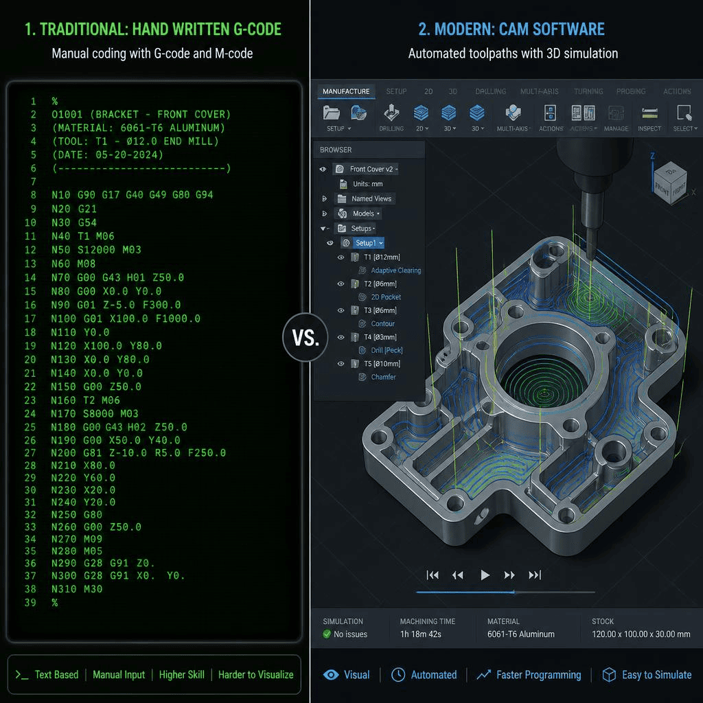
There are two fundamentally different approaches to generating a CNC program, and most real production work uses some combination of both.
Manual programming means writing G-code and M-code directly, by hand, based on the part geometry and the machining operations required. It's genuinely practical for simple parts — a straightforward facing pass, a basic drilled hole pattern — where the toolpath is simple enough to calculate and write out without much risk of error. For complex 3D geometry, manual programming becomes impractical fast; nobody is hand-writing the thousands of coordinated points needed for a contoured surface.
CAM (Computer-Aided Manufacturing) software generates the program automatically from a CAD model. The programmer defines the operations — which faces to mill, what tool to use, what stepover and depth of cut — and the CAM software calculates the actual toolpath and generates the G-code. This is how the overwhelming majority of real production programming happens today, since it scales to complex geometry that manual programming simply can't handle efficiently. Our guide on CAM software and CNC machining covers how this workflow actually operates, and our guide to choosing free CAM software covers options for getting started without a major software investment.
Conversational or graphic programming, built into some machine controllers, sits between the two — the operator inputs part features through a guided interface rather than writing raw code or running full CAM software, and the controller generates the program internally. It's common on simpler machines and for shops running frequent, straightforward jobs where a full CAM workflow would be overkill.
G-Code and M-Code: The Language of CNC Programming
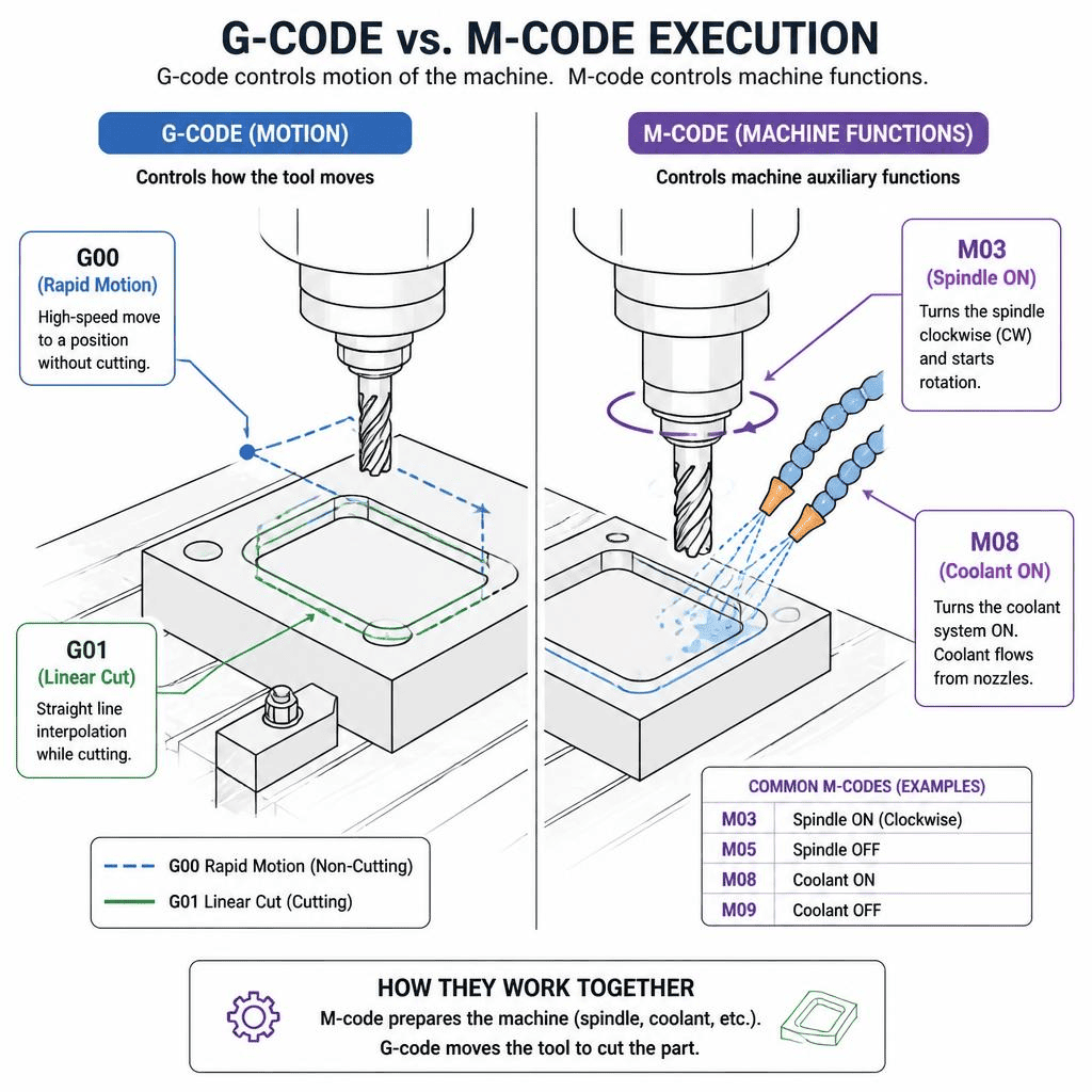
Underneath every CAM-generated program, and every manually written one, is G-code and M-code — the actual instruction set the machine executes.
G-code controls geometric motion: where the tool goes and how it gets there. Commands like G00 (rapid positioning, moving quickly with no cutting) and G01 (linear interpolation, cutting in a straight line at a controlled feed rate) form the backbone of tool movement, along with codes for circular interpolation, canned cycles for repetitive operations like drilling, and coordinate system setup.
M-code controls the machine's auxiliary functions — spindle on/off and direction, coolant on/off, tool changes, program stops. Where G-code answers "where does the tool go," M-code answers "what else does the machine need to do around that movement."
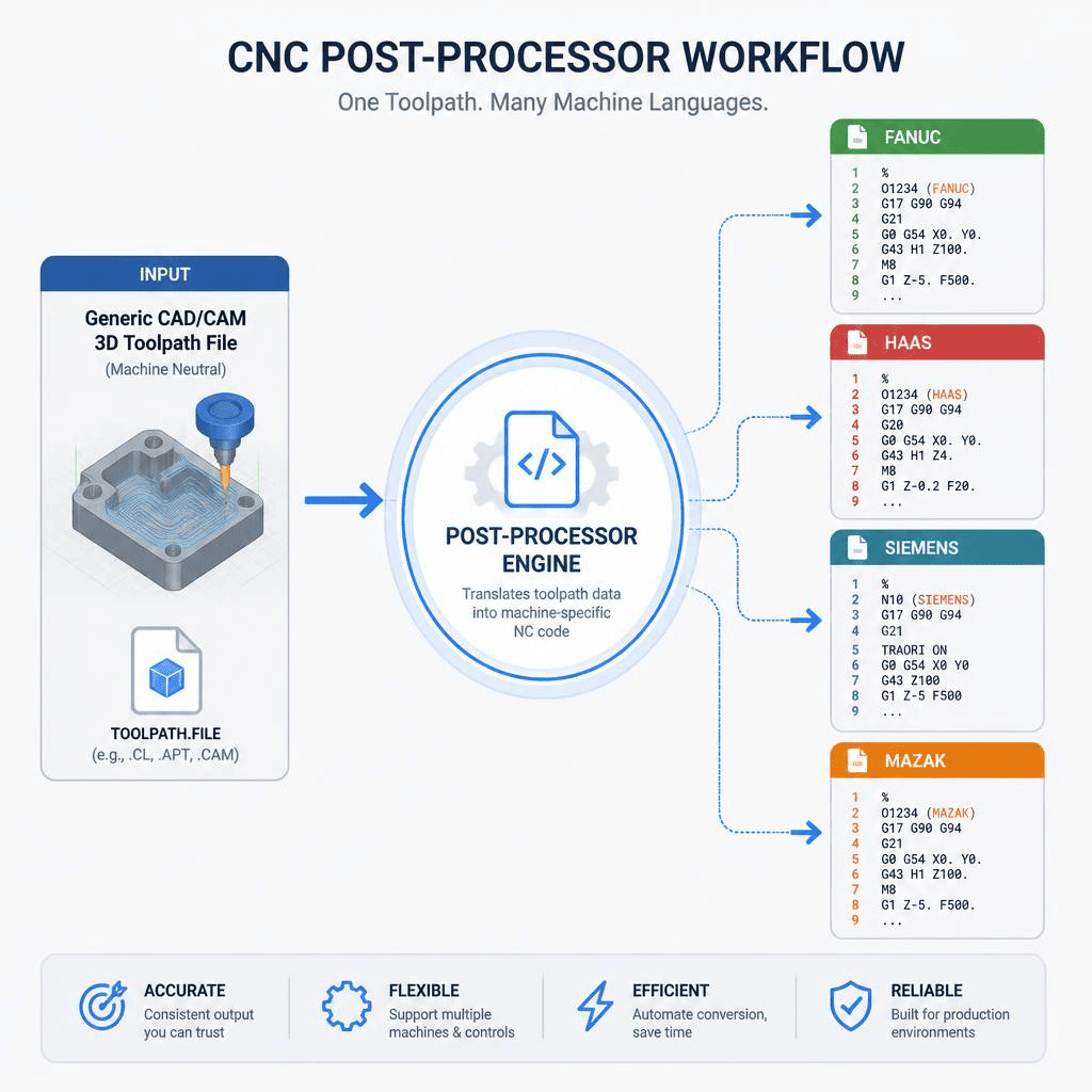
These aren't universal across every machine — different controllers (Fanuc, Siemens, Haas, Mazak, and others) have their own dialects and quirks even though the core G/M-code structure is broadly standardized. Our beginner's guide to G-code and M-code breaks down the most common commands and how they work together in an actual program.
From CAM Toolpath to Machine-Ready Code: The Post-Processor
CAM software generates a toolpath in a generic, machine-independent format first. The post-processor is what translates that generic toolpath into the specific G-code dialect a particular machine and controller actually understands — accounting for that machine's specific command syntax, axis configuration, and controller quirks. A toolpath that's perfectly correct in the CAM software can still fail on the shop floor if the wrong post-processor is applied, or if the post-processor isn't properly configured for that specific machine. Our guide on what a CNC post-processor is and how it works covers this translation step in more depth — it's a step that's easy to overlook but genuinely determines whether a program runs correctly on the actual machine it's destined for.
Toolpath Strategy: The Programming Decisions That Actually Matter
Generating code that runs is only part of the job — generating code that produces a good part efficiently is where real programming skill shows up. A few of the key decisions:
Stepover — the lateral distance between successive toolpath passes — directly affects surface finish, machining time, and tool wear. A smaller stepover produces a finer finish at the cost of more passes and longer cycle time; a larger stepover cuts faster but leaves a rougher surface. Our guide on what stepover means in CNC machining covers how to balance this tradeoff for roughing versus finishing operations.
Toolpath strategy more broadly — how the tool approaches and traverses the part geometry — has a real effect on cycle time, tool life, and surface quality, and it's rarely a single obvious choice. Our guide to what a CNC toolpath actually is covers how toolpath decisions affect accuracy, efficiency, and finish across different operation types.
High-Speed Machining (HSM) & Trochoidal Milling: Instead of plowing into tight corners with heavy radial engagement, modern CAM relies on constant-engagement trochoidal toolpaths. This allows the tool to use its full flute length at high feed rates, dramatically extending tool life and reducing cycle time, especially in hard metals.
Tool path optimization — refining a working toolpath further, rather than accepting the first version that produces a correct part — is where a lot of real production cost savings live, especially at volume where small cycle-time improvements compound across thousands of parts. Our guide to tool path optimization in CAM software covers this in more depth.
Common Mistakes in CNC Programming
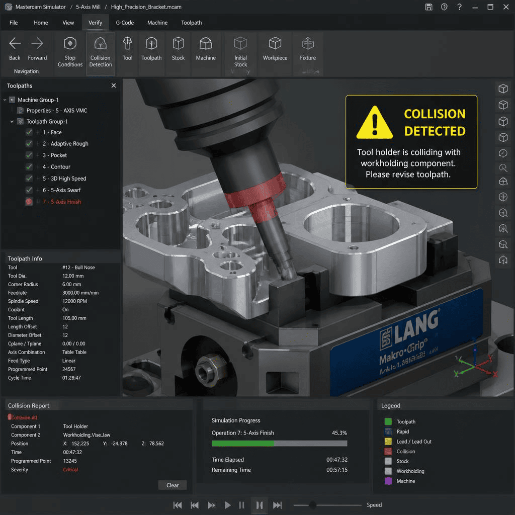
Skipping simulation before running a program on the actual machine is one of the most expensive habits in programming — a collision between the tool and a clamp, fixture, or the machine itself is far cheaper to catch in software than on the shop floor, where it can damage the tool, the machine, or the part. Most CAM software includes simulation specifically to catch this before a program ever reaches a real machine.
Assuming a program that works on one machine will run identically on another is a related mistake — different controllers, different post-processors, and even different machine tolerances mean a program genuinely validated on Machine A needs re-verification, not just a file copy, before running on Machine B.
Treating programming as a one-time task rather than something worth refining is a subtler mistake, particularly at production volume. A program that produces a correct part on the first run isn't necessarily an efficient program — cycle time, tool wear, and surface finish can often improve meaningfully with a second pass at optimization once the process is proven correct.
Learning CNC Programming
If you're looking to actually learn CNC programming rather than just understand how it fits into a manufacturing workflow, our step-by-step guide to learning CNC programming walks through a practical path from the fundamentals through to a working skill set — a different, more hands-on resource than this overview.
Need CNC Machining for Your Next Project? Upload your CAD file today to get an instant quote for precision CNC milling and turning.
FAQ
Do I need to learn G-code to order CNC machined parts?
No — an engineer or designer sourcing CNC machined parts doesn't need to read or write G-code directly. Understanding the basics of how programming affects cost, feasibility, and lead time is useful, but the actual programming is the manufacturer's job.
What's the difference between CAM software and manual programming?
Manual programming means writing G-code by hand, practical for simple operations. CAM software generates the toolpath and code automatically from a CAD model based on operations the programmer defines, and is what nearly all complex or production programming relies on today.
Is G-code the same on every CNC machine?
The core structure is broadly standardized, but different machine controllers have their own dialects, supported commands, and quirks. This is exactly why post-processors exist — to translate a generic CAM toolpath into the specific code a given machine and controller actually need.
What does a post-processor actually do?
It translates the generic toolpath a CAM system generates into the specific G-code syntax and format required by a particular machine and controller, accounting for that machine's axis configuration and command dialect.
Popular Articles
• Are There Any Design Limitations or Restrictions for CNC Machining
• From CAD to CNC The Importance of Accurate 3D Modeling in Manufacturing
• Understanding CNC Machine Tolerances and Their Impact on Part Accuracy
• How to Learn CNC Programming: A Step-by-Step Guide for Beginners
• G and M code: a beginner's guide to CNC programming language
Keep Learning
Are There Any Design Limitations or Restrictions for CNC Machining
Quick Answer: CNC design is limited mainly by tool access, cutter radius, part rigidity, workholding, machine travel, material behavior, and tolerance requirements. Review those constraints before finalizing CAD, especially for deep pockets, thin walls, internal corners, undercuts, small threads, and critical fits. A design that looks completely reasonable in CAD can turn out to be genuinely difficult — or impossible — to machine as drawn. Not because the geometry is wrong in any absolute sense, but b......
GD&T in CNC Machining: Everything You Need to Know.
Why Does GD&T Matter in CNC Manufacturing? (autodesk) What is GD and T? Ask five machinists to interpret a drawing without it and you might end up with five completely different parts. That's because traditional linear dimensions and notes can only go so far, leaving plenty of room for misinterpretation. This is where GD&T (Geometric Dimensioning and Tolerancing), the universal language of engineers, is used to define how a part should truly function and fit. At its core, GD&T is a symbolic system tha......
What Is CNC Programming? A Complete Guide
What Is CNC Programming? A Complete Guide A finished CAD model doesn't cut anything by itself. Between a 3D design sitting on a screen and an actual part coming off a machine, there's a translation step that turns geometry into motion — where the tool goes, how fast it moves, when it changes, when coolant kicks on. That translation is CNC programming, and it's easy to take for granted until something in it goes wrong: a program that runs a toolpath through a clamp, a feed rate that's fine on paper but......
From CAD to CNC The Importance of Accurate 3D Modeling in Manufacturing
In modern manufacturing, the process from CAD design to CNC machining is an indispensable part of producing high-quality parts and products, and 3D modelling, as a core part of this process, has a direct impact on the accuracy, functionality and appearance of the final product. In this article, we will discuss the CAD to CNC process, analyse the importance of accurate 3D modelling, and share how to optimise the modelling process to improve manufacturing efficiency and product quality. I. CAD design: l......
What Is Stepover in CNC Machining? Meaning, Surface Finish, and Toolpath Strategy
Stepover in CNC machining refers to the lateral distance a cutting tool moves between successive passes. It is a key parameter in CNC toolpaths that directly affects surface finish, machining time, and tool wear. Understanding what stepover in CNC means is essential for optimizing both roughing and finishing operations in milling processes. What Stepover Means in CNC Toolpaths? CAM toolpath illustrating stepover in CNC machining. (Source: chrisandjimcim.com) Efficient milling requires long-term precis......
From STP File to Finished Part How Online CNC Machining Brings Your CAD Model to Life
Driven by intelligent manufacturing and industrial internet, CNC machining is innovating from traditional mode to digitalization and visualization. As the “international language” for product data exchange, STP file (STEP/STP format) has become the core bridge connecting design and manufacturing due to its high compatibility and integrity. In this article, we will explain how to realize the whole process management from STP files to finished parts through online visualization technology, covering key ......