What Is Design for X (DFX)? Principles, Types & Applications
16 min
- What Is Design for X (DFX)?
- What Are the Main Types of DFX?
- Why Is DFX Important in Product Development?
- How Is DFX Applied to CNC Manufacturing?
- DFX vs. DFM: What Is the Difference?
- DFX FAQs
- Conclusion: Applying DFX in Product Design
Key Takeaways
- A part can work exactly as intended and still create problems in manufacturing, assembly, inspection, service, or cost. DFX brings these downstream considerations into the design stage, while design changes are still relatively easy to make.
- DFX principles don't replace functional requirements. They identify where those requirements create downstream problems and find ways to resolve the conflict before tooling, production, or launch.
- DFX is not a single method. It's a collection of overlapping disciplines (DFM, DFA, DFC, DFR, and others) applied iteratively throughout product development.
- DFX in CNC manufacturing translates into decisions about feature geometry, tolerances, tool access, datums, and inspection that affect whether a design can be machined and verified reliably.
- DFM is one discipline within the broader DFX engineering framework.
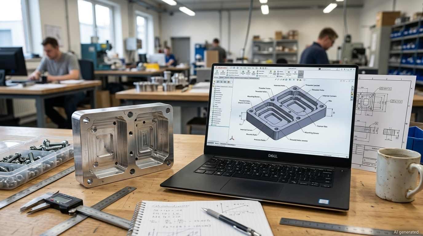
Design for X (DFX) is considered during the design stage.
Every engineer has experienced it. A design gets through review, goes to manufacturing, and then the problems start. The pocket is too deep for the available tooling. The tolerance stack-up creates an inspection nightmare. The assembly sequence requires three hands. The part can't be serviced in the field without disassembling everything around it.
These issues are usually discovered during manufacturing, but many of them originate in earlier design decisions that were not evaluated against production or service requirements. Design for X (DFX) exists to find these problems at the concept stage, when the design is still relatively easy to change, rather than after tooling, qualification, or production commitments have made the same change substantially more costly.
What Is Design for X (DFX)?
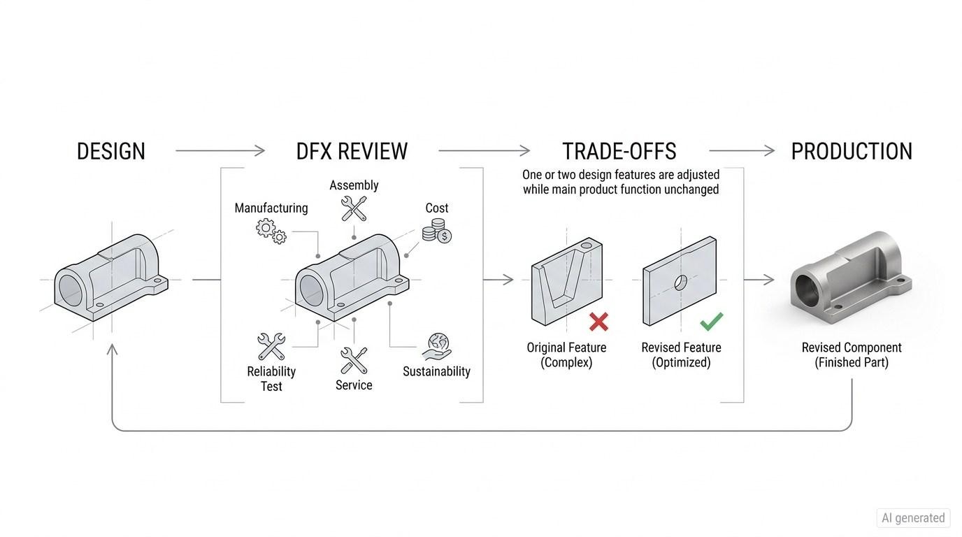
Design for X (DFX) is an engineering approach that evaluates a product design against a specific downstream objective, such as manufacturability, assembly, cost, reliability, testability, serviceability, or inspection. The "X" identifies the objective being optimized.
Design for X (DFX) is widely used as an umbrella term for design approaches that optimize a product for a specific downstream objective. In some engineering literature, DFX is also expanded as Design for Excellence, while specific disciplines are named directly, such as Design for Manufacturing (DFM) or Design for Assembly (DFA). Terminology varies by organization and industry, so the exact list of DFX disciplines is not universal.
What Are the DFX Principles in Product Development?
There is no single standardized three-step DFX process. In practice, DFX reviews typically define the target X, evaluate the design against relevant criteria, and resolve conflicts before downstream commitments are made.
1Identify DFX Objectives and Requirements
The first step is understanding what "X" actually requires. For DFM, that means understanding what the manufacturing process can and can't do, the tolerances it achieves, the geometries it handles, the materials it accepts. For DFR (reliability), it means understanding the stress environment the product will see and the failure modes most likely to limit service life. For DFC (cost), it means identifying where the cost drivers are in the product's production chain.
This step produces the DFX criteria against which the design will be evaluated, the specific, quantified requirements that downstream success depends on. Without this step, DFX engineering becomes vague. A manufacturing engineer saying "this will be hard to make" isn't DFX. An engineer saying "this 0.5mm wall section will deflect during this operation, producing dimensional variation outside the part's tolerance requirement" is DFX, specific, causal, and actionable.
2Evaluate the Design Against DFX Criteria
With the criteria established, the design is evaluated systematically against each one. This is where design for X generates its value, not by approving or rejecting the design wholesale, but by identifying specific features or decisions that conflict with downstream requirements.
A bore that's too deep for the available tooling length. A tolerance that's achievable in principle but requires 100% inspection at a cost the program budget doesn't support. A fastener location that requires removing six other components to access during service. Each of these is a specific DFX finding rather than a general concern.
DFX principles across all disciplines share the same evaluation logic: map every design feature or decision to its downstream consequence, quantify the consequence where possible, and rank findings by impact to focus resolution effort.
3Resolve Trade-Offs Before Production
A tight tolerance is specified because the function requires it, but the manufacturing cost it produces is significant. The resolution isn't simply "loosen the tolerance." It's a conversation between functional requirements and production constraints: is there a geometry change that delivers the function with a looser tolerance? Is there a different process that achieves the tolerance at lower cost? Is the tolerance correct, or is it inherited from an earlier design without re-evaluation?
DFX engineering is effective when these conversations happen during design. The same problem becomes progressively more expensive to resolve as the design moves toward tooling, qualification, and production because more downstream work is already committed. The tooling exists, the schedule is committed, and every change requires re-qualification.
Engineering Note
One of the practical reasons for applying DFX early is that the cost and impact of a design change generally increase as downstream work becomes committed. The effort required to change a design generally increases as tooling, qualification, procurement, and production activities become committed. Changes made early in development usually involve fewer downstream dependencies than changes made after release or production launch.
What Are the Main Types of DFX?
There's no single canonical list of DFX types. Different organizations, industries, and programs apply different sets of design for X disciplines depending on what matters for their products. The disciplines below are the most commonly applied in engineering product development, not an exhaustive fixed taxonomy.
| DFX Discipline | Full Name | Primary Design Objective | Downstream Concern Addressed |
|---|---|---|---|
| DFM | Design for Manufacturing | Design parts that can be made accurately and efficiently | Manufacturability, process capability, tooling, cycle time |
| DFA | Design for Assembly | Minimize assembly complexity and error opportunity | Assembly time, error rate, sequence constraints |
| DFC | Design for Cost | Control cost drivers during design rather than after | Unit cost, tooling investment, overhead |
| DFR | Design for Reliability | Design failure modes out of the product | Field failure rate, warranty, safety margin |
| DFT | Design for Testability | Ensure the product can be tested effectively | Test coverage, time, and cost |
| DFS | Design for Serviceability | Enable efficient field service and repair | Downtime, service cost, technician complexity |
| DFE | Design for Environment | Minimize environmental impact across the product lifecycle | Material choice, energy, recyclability, compliance |
| DFI | Design for Inspection | Ensure critical features can be measured reliably | Datum accessibility, gauge access, CMM access, measurement capability |
Design for Manufacturing (DFM)
DFM is the discipline most engineers encounter first because manufacturing problems are visible early and have immediate schedule and cost consequences. DFM asks whether the design can be produced, by the intended process, to the required tolerances, in the required material, at the required volume, and identifies where the answer is no or only with significant effort.
DFM is one of the most direct applications of DFX in CNC manufacturing because machining constraints can often be traced directly to specific design features. It addresses feature geometry, wall thickness, pocket depth, internal corner radii, hole aspect ratios, tolerances relative to process capability, material machinability, and fixturing requirements. These aren't aesthetic preferences. They're quantifiable constraints that determine whether production is straightforward or problematic.
Design for Assembly (DFA)
DFA evaluates whether each part and assembly operation is necessary, practical, and economical for the intended assembly process. DFA asks whether parts can be consolidated, whether assembly sequences are logical, whether connections are mistake-proof, and whether human or automated assembly can be reliably achieved.
The DFA result isn't always fewer parts. Sometimes a feature that DFA would consolidate must remain separate for service access (a DFS requirement). DFX engineering is partly about managing these conflicts between disciplines.
Design for Cost (DFC)
DFC makes explicit what most engineering decisions imply but often don't quantify: every design choice has a cost consequence. A surface finish specification adds a secondary operation. A tight tolerance can increase inspection requirements, particularly when process capability is limited or the feature is critical to product performance. A non-standard material adds procurement lead time and cost. DFC makes these consequences visible during design so trade-offs can be made deliberately.
Design for Reliability (DFR)
DFR addresses the failure modes that functional design tends to underestimate. A feature that meets its static load requirement may not meet its fatigue life requirement. A seal that works in testing may not work across the full temperature range in service. DFR may use tools such as FMEA, physics-of-failure analysis, reliability prediction, stress-strength analysis, and accelerated testing to identify failure mechanisms and build adequate reliability margin into the design.
Design for Testability (DFT)
A product that can't be efficiently tested can't be confidently shipped. DFT ensures that critical functional parameters can be measured, that test points are accessible, that the test process is repeatable, and that the cost of testing is proportional to the risk being managed. In electronics, this means physical test point access.
For mechanical products, DFT can involve access to test interfaces, sensors, functional test points, and other features needed to verify performance. Dimensional measurement and CMM probe access are more directly related to design for inspection.
Design for Serviceability (DFS)
Field service problems are often designed in. A component that fails in service but requires complete disassembly to replace, because the designer never considered service access, is a DFS failure. DFS asks how the product will be maintained, what will fail, how often, and whether field replacement is practical. The answers influence fastener selection, access geometry, module boundaries, and spare parts strategy.
Design for Environment (DFE)
Design for Environment considers environmental impacts across the product life cycle, including material selection, manufacturing, use, reuse, recycling, and end-of-life processing.
Design for Inspection (DFI)
DFI focuses on making critical product features practical to inspect and verify after manufacturing. It considers whether datums and features are accessible with the planned inspection method and whether the specified tolerances can be verified with adequate measurement capability. For CNC-machined parts, this can influence datum placement, probe clearance, feature accessibility, and the choice of inspection method.
Why Is DFX Important in Product Development?
DFX matters because many downstream costs are determined by design decisions made before production begins.
DFX does not guarantee a successful product. It changes when downstream risks are identified and addressed. Downstream problems that DFX finds during design are resolved cheaply. Downstream problems that DFX misses, or that a program skips DFX to avoid addressing, surface in production, field returns, or warranty claims, where they're expensive, visible, and often traced back to design decisions that an earlier DFX review would have caught.
DFX is most effective when applied iteratively rather than as a single review before release. A concept-stage review addresses major design decisions, while later reviews focus on features, tolerances, and production requirements.
For CNC-machined parts, DFX often comes down to whether the design can be machined and verified as intended. A DFM review helps identify potential manufacturing issues before they affect production.

Precision CNC Machining Service
Upload your CAD file to JLCCNC for a project-specific engineering review and CNC machining quote.
How Is DFX Applied to CNC Manufacturing?
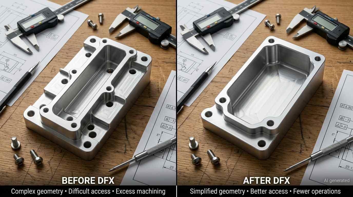
Applying Design for X (DFX) on a CNC-machined mechanical component.
CNC machining is a concrete example of where DFX engineering translates directly into specific design decisions, because the constraints of the process are well-defined and the consequences of ignoring them are quantifiable.
DFX Considerations for CNC Machined Parts
Tool access is the most fundamental DFX constraint in CNC machining. A feature that requires a tool orientation the machine can't achieve, or that's in a location the workholding prevents access to, either can't be machined or requires a setup that multiplies cost. Design for X in CNC manufacturing means evaluating tool access for every feature before the drawing is released, not after the machinist asks the question.
Internal corner radii deserve specific attention. A true sharp internal corner cannot be produced with a conventional round end mill. It usually requires a non-rotary process, such as EDM, or a design change that introduces a corner radius or relief. Smaller end mills can reach tighter radii, but they also increase machining time and tool-load sensitivity. Choosing an internal radius that is compatible with the available tooling can allow a larger cutter and more stable cutting conditions. If the mating geometry does not require a small radius, increasing the internal radius can allow a larger cutter and reduce machining difficulty without changing the intended function. DFX engineering identifies this trade-off during design.
Wall thickness and pocket depth interact with deflection and vibration during machining. Thin walls in tall, narrow pockets deflect under cutting forces, producing dimensional variation that the tolerance can't absorb. This isn't a machinist problem. It's a design problem that shows up on the shop floor. The DFX question is whether the feature can be machined with sufficient stiffness and tool access to hold the specified tolerance without excessive passes, reduced cutting conditions, or additional setups.
Datum strategy is a DFX consideration that connects manufacturing and inspection. If the drawing defines a datum that's difficult to locate or that requires the part to be re-fixtured between machining and inspection, both processes are slower and more expensive than they need to be. A DFX review evaluates whether the datum scheme is accessible and stable during machining and whether the same functional references can be established reliably during inspection.
Designing for Manufacturing and Inspection
A part that's manufacturable but not inspectable is a production problem waiting to happen. DFX engineering considers both simultaneously. Can the critical dimensions be measured with standard gauging? If a CMM is required, is there clear probe access to the features that matter? If the tolerance is tight, is the measurement uncertainty of the available inspection equipment adequate to make meaningful conformance decisions?
Balancing Function, Cost, and Production Requirements
A practical DFX example from CNC manufacturing is a pattern of threaded holes with a tight positional requirement. The requirement may be functionally justified by the mating component, but the inspection method and production cost depend on the actual tolerance zone, datum scheme, process capability, and available gauging. A DFX review can therefore ask whether the mating geometry can provide more positional clearance, allowing a less restrictive tolerance without affecting assembly or alignment. The result may be a simpler machining and inspection process while preserving the functional requirement.
DFX vs. DFM: What Is the Difference?
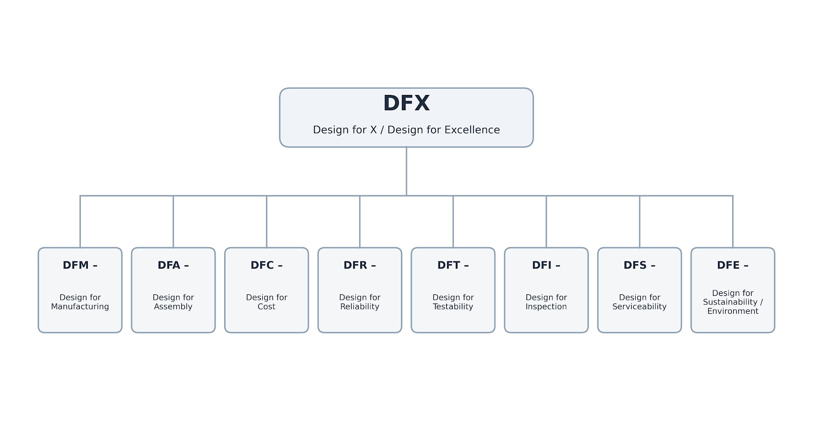
DFX hierarchy
This is one of the most common points of confusion in engineering practice. DFM and DFX are used interchangeably in some organizations, which obscures a meaningful distinction.
DFM is a specific DFX discipline focused on manufacturability. DFX is broader and can address manufacturing, assembly, inspection, cost, reliability, serviceability, and other downstream objectives.
| Factor | DFX (Design for X / Design for Excellence) | DFM (Design for Manufacturing) |
|---|---|---|
| Scope | Broad framework covering any downstream concern | Specific discipline focused on manufacturability |
| Relationship | DFX is commonly used as the broader umbrella term | DFM is commonly treated as one DFX discipline. |
| Covers | Manufacturing, assembly, cost, reliability, testability, serviceability, sustainability | Manufacturing process capability, geometry, tolerances, material, tooling |
| When applied | Throughout product development, all design stages | Primarily at detail design and drawing release |
| Who leads | Cross-functional (design, manufacturing, quality, service) | Primarily manufacturing/design engineering |
| Interchangeable with DFX? | No, DFX is the broader category | No, DFM is a subset of DFX |
For detailed DFM guidance specific to CNC machining, see the design for manufacturing guide at JLCCNC, which covers process-specific DFM rules, cost analysis, and tolerance decision-making in depth.
Engineering Note
DFX decisions are application-dependent. The appropriate design criteria vary with the manufacturing process, product function, production volume, inspection requirements, and service environment.
DFX FAQs
Q: What are the most common types of DFX?
The most commonly applied DFX disciplines include DFM (Design for Manufacturing), DFA (Design for Assembly), DFC (Design for Cost), DFR (Design for Reliability), DFT (Design for Testability), DFS (Design for Serviceability), DFI (Design for Inspection), and DfE (Design for Environment). The exact set varies by product and industry.
Q: Is DFX the same as DFM?
No. DFX is the broader framework that includes DFM as one specific discipline. DFM addresses manufacturability, whether and how a design can be produced. DFX addresses manufacturability plus assembly, cost, reliability, testability, serviceability, sustainability, and any other downstream concern relevant to the product. Using DFM and DFX interchangeably understates the scope of what DFX principles cover and misses downstream risks that DFM alone doesn't address.
Q: When should DFX be applied?
DFX is most effective when applied iteratively throughout product development, from concept stage (where major process, part consolidation, and cost decisions are made) through detail design (where specific features, tolerances, and production requirements are finalized). A single DFX review at drawing release catches some problems but misses the decisions made earlier that are now locked in. Design for excellence works best as a continuous conversation between design and downstream engineering functions, not a gate-based review.
Q: What is an example of DFX in manufacturing?
A classic DFX engineering example in CNC manufacturing: a part has a deep narrow pocket with sharp internal corners. The functional requirement is a smooth internal surface for a sealing component. DFX review identifies that the sharp corners require EDM or very small tooling at high cost, while a 2mm fillet radius would allow standard end milling at a fraction of the cost. Further review confirms the seal geometry accommodates a 2mm radius without compromising sealing performance. The design change is made during detail design, with no production disruption, no tooling modification, significant per-part cost reduction that scales across the production volume.
Conclusion: Applying DFX in Product Design
Design for X brings downstream engineering requirements into the design process while changes are still relatively easy to make. A design can meet its functional requirements and still create problems later in manufacturing, inspection, assembly, or service. DFX helps identify these issues before they become production constraints.
For CNC-machined parts, this means considering the machining and inspection process while the design is still being developed. A feature that looks acceptable on a drawing may be difficult to machine or verify because of its geometry, tolerance, or access requirements.
Precision CNC Machining Service
JLCCNC provides engineering review for CNC machining projects to identify manufacturability concerns before production. Upload your CAD file to receive a project-specific review and CNC machining quote.
Keep Learning
GD&T Datum: Definition, Types, Symbols, and Datum Reference Frame
Key Takeaways A datum in GD&T is a theoretically exact reference used to locate or orient other features on a part. It is not the physical surface itself. A datum feature is the physical feature identified on the part and used to establish a datum. The datum itself is the theoretically exact geometric reference derived from that feature. Datums become especially important when several features have to work together. A hole pattern, bearing bore, mounting face, or mating surface may need to establish t......
GD&T Runout: Definition, Symbol, Measurement & Tolerance
Key Takeaways Runout limits surface variation while a part rotates around its specified datum axis. The datum feature establishes the axis used for the runout requirement. You compare the full indicator variation during rotation with the tolerance stated on the drawing. Circular runout applies at individual circular sections of the controlled surface. Total runout evaluates the controlled surface across its specified extent. Runout is not a size tolerance, and its value is not determined by the diamet......
GD&T Perpendicularity: Definition, Tolerance & Examples
Key Takeaways Perpendicularity is an orientation control used for a feature specified at 90° to a datum. A surface callout controls the complete surface within two parallel planes set perpendicular to the referenced datum. An axis callout controls the derived axis inside the specified tolerance zone instead of controlling the physical surface directly. Perpendicularity does not establish the location of a feature. A drawing can require another geometric control when position also needs definition. Dat......
Concentricity in GD&T: Definition, Symbol, Tolerance, and Measurement
Key Takeaways Concentricity in legacy ASME GD&T controls the derived median points of a feature relative to a datum axis. It does not simply compare the axes of two fitted cylinders. Check the drawing standard first. Legacy ASME concentricity and ISO concentricity or coaxiality should not be interpreted as equivalent requirements. For the cylindrical example in this guide, the tolerance zone is a cylinder centered on the datum axis. The derived median points of the controlled feature must lie within t......
Engineering Fits: Clearance, Transition, and Interference Fits
Key Takeaways Engineering fits describe the dimensional relationship between two mating parts, specifically whether assembly produces clearance (gap), interference (overlap), or a result that could be either. Clearance fit always produces a gap; the shaft is always smaller than the hole. Interference fit always produces overlap; the shaft is always larger than the hole and force or temperature is needed to assemble. Transition fit can produce either a small clearance or small interference depending on......
What Is Design for X (DFX)? Principles, Types & Applications
Key Takeaways A part can work exactly as intended and still create problems in manufacturing, assembly, inspection, service, or cost. DFX brings these downstream considerations into the design stage, while design changes are still relatively easy to make. DFX principles don't replace functional requirements. They identify where those requirements create downstream problems and find ways to resolve the conflict before tooling, production, or launch. DFX is not a single method. It's a collection of over......