Maximum Material Condition (MMC) in GD&T
17 min
- What Is Maximum Material Condition (MMC)?
- MMC Symbol and GD&T Drawing Callouts
- MMC Bonus Tolerance and Virtual Condition
- MMC vs LMC vs RFS in GD&T
- Common MMC Applications in Engineering Drawings
- How MMC Affects CNC Machining and Inspection
- Common MMC Interpretation Mistakes
- Maximum Material Condition FAQs
Key Takeaways
- MMC is the condition in which a feature of size contains the maximum amount of material within its specified size limits. For a shaft or pin, this is the largest permitted size; for a hole, it is the smallest permitted size.
- MMC is used with features of size, such as holes, shafts, pins, and slots.
- When the MMC symbol Ⓜ is added to a geometric tolerance, the feature can gain bonus tolerance as its actual size moves away from MMC.
- MMC is commonly applied to holes, pins, and other mating features where their size and position affect the fit.
- Bonus tolerance and virtual condition help determine the usable limit of an MMC-controlled feature during inspection and assembly checks.
- When reading the drawing, check the feature size limits and the MMC symbol together. The MMC callout works with those limits; it does not simply mean that the feature should be made as large or as small as possible.
When a hole and a pin have to fit together, checking the basic dimensions alone does not tell the whole story. Their actual sizes can vary within the limits on the drawing, and that variation can affect the amount of positional error that the feature can accept.
This is where Maximum Material Condition (MMC) is used in GD&T.
For a hole, MMC is the smallest allowed hole because a smaller hole diameter means more material remains around the hole. For a shaft or pin, MMC is the largest allowed diameter because more material is present at that size.
MMC becomes especially useful when a geometric tolerance, such as position, is allowed to increase as the feature moves away from its MMC size. This additional amount is called bonus tolerance.
For example, consider a hole specified as Ø10.00 ±0.10 mm with a position tolerance of Ø0.20 mm Ⓜ. The MMC size of the hole is 9.90 mm. If the actual hole is measured at 10.00 mm, it has moved 0.10 mm away from MMC. That 0.10 mm can be added to the stated position tolerance, giving a total available position tolerance of Ø0.30 mm.
This relationship matters during inspection because the available geometric tolerance depends on the feature's departure from MMC when the MMC modifier is specified.
What Is Maximum Material Condition (MMC)?
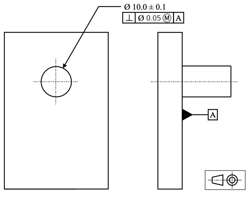
Maximum Material Condition (MMC) - GD&T Basics
Maximum Material Condition (MMC) is the condition in which a feature of size contains the maximum amount of material within its specified limits of size.
MMC is determined from the limits of size specified on the drawing, not from the nominal or basic size.
MMC for Holes and Shafts
The direction of MMC depends on whether the feature is an internal feature or an external feature.
For a hole, the smallest permitted diameter represents MMC. A smaller hole leaves more material around the opening.
For a shaft or pin, the largest permitted diameter represents MMC. A larger shaft means more material is present in the feature.
For example:
- Hole: Ø10.00 ±0.05 mm: limits are 9.95 to 10.05 mm: MMC = 9.95 mm
- Shaft: Ø10.00 ±0.05 mm: limits are 9.95 to 10.05 mm: MMC = 10.05 mm
This is the value to use when interpreting an MMC-based GD&T requirement. The actual measured size can then be compared with MMC to determine whether additional geometric tolerance is available under the applicable callout.
MMC Symbol and GD&T Drawing Callouts
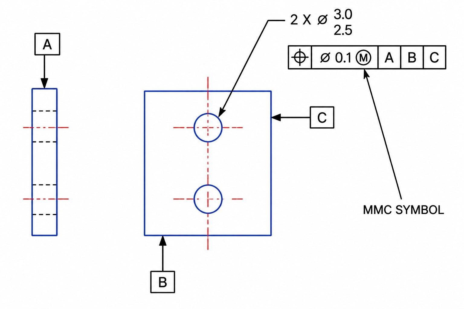
MMC callout symbol (eMachineShop.com)
The MMC requirement is shown directly in the feature control frame using the material condition symbol Ⓜ. The MMC symbol indicates that the stated geometric tolerance applies when the feature is at its MMC size. As the feature departs from MMC toward LMC, an equivalent amount of additional geometric tolerance may become available as bonus tolerance.
How MMC Is Shown on GD&T Drawings
For a feature of size, the MMC symbol Ⓜ is placed after the applicable geometric tolerance value in the feature control frame. It indicates that the stated geometric tolerance applies at MMC and that departure from MMC can provide bonus tolerance.
For example:
Position | ⌀0.20 | Ⓜ
Here, ⌀0.20 is the stated position tolerance, and Ⓜ indicates that it is applied at MMC.
For a hole, first determine its MMC from the size limits. For a shaft or pin, determine MMC from the opposite direction. The MMC symbol itself does not change the feature's size limits shown on the engineering drawing.
How MMC Modifies GD&T Feature Control Frames
The MMC modifier becomes important when the actual size of the feature differs from its MMC size.
For example, consider:
Ø10.00 ±0.05
Position | ⌀0.20 | Ⓜ
The hole's MMC is 9.95 mm. If the manufactured hole measures 9.95 mm, the available position tolerance is the stated ⌀0.20 mm.
If the hole measures 10.00 mm, it has 0.05 mm of size departure from MMC. Under the MMC rule, that departure provides 0.05 mm of additional position tolerance, giving a total of ⌀0.25 mm.
MMC Bonus Tolerance and Virtual Condition
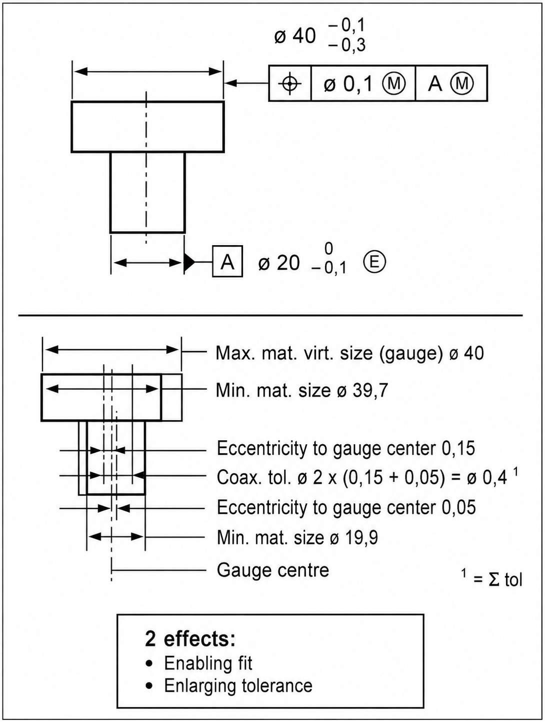
Maximum material condition MMC along with reciprocity requirement RPR (ScienceDirect)
When the MMC modifier Ⓜ is applied to a geometric tolerance, the allowable geometric variation is not necessarily fixed at one value. It depends on how far the actual feature size moves away from its MMC size.
This creates two related concepts: bonus tolerance and virtual condition.
Bonus Tolerance in MMC
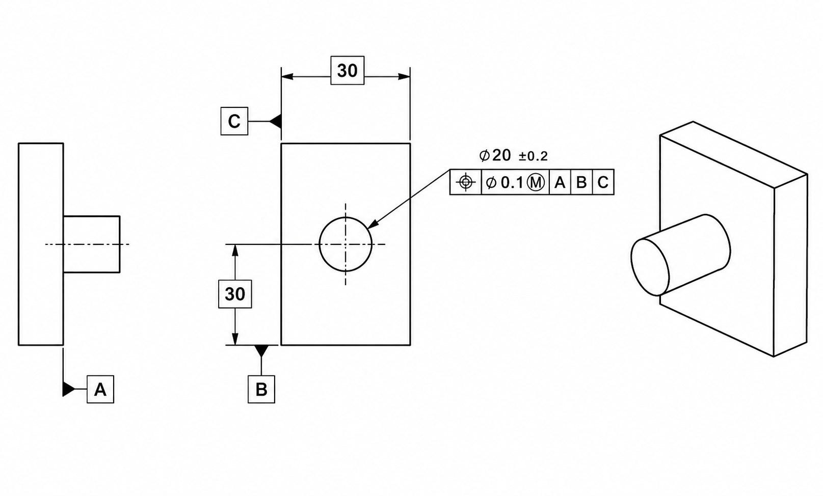
GD&T bonus tolerance (Mechademic)
Bonus tolerance is the additional geometric tolerance obtained when the actual feature size moves away from MMC.
For a cylindrical feature controlled with a diametric geometric tolerance, bonus tolerance is based on the feature's diametric departure from MMC:
Hole: Bonus tolerance = Actual size − MMC size
Shaft or pin: Bonus tolerance = MMC size − Actual size
For non-cylindrical features or cases involving significant form variation, the applicable drawing requirements should be evaluated using the rules of the specified ASME Y14.5 edition rather than relying on a single size measurement.
Bonus Tolerance Calculation With a Worked Example
Consider a hole with:
- Size: Ø10.00 ±0.05 mm
- MMC: Ø9.95 mm
- Position tolerance at MMC: ⌀0.20 mm
- Actual hole size: Ø10.00 mm
First, find the difference between the actual hole size and its MMC size:
10.00 − 9.95 = 0.05 mm
The 0.05 mm departure from MMC provides 0.05 mm of additional positional tolerance-zone diameter.
Add the bonus tolerance to the position tolerance stated at MMC:
0.20 + 0.05 = ⌀0.25 mm
So, with the hole measured at Ø10.00 mm, the total available position tolerance is ⌀0.25 mm.
If the hole is measured at its MMC size of Ø9.95 mm, there is no departure from MMC. The available position tolerance remains ⌀0.20 mm.
This is the key calculation to use when checking an MMC-controlled hole: actual feature size − MMC size = bonus tolerance; then add that bonus to the stated geometric tolerance.
Virtual Condition and Assembly Requirements
Virtual Condition (VC) is a fixed boundary generated by the MMC size of a feature of size and the applicable geometric tolerance. The actual feature must remain within the applicable virtual condition boundary.
For a cylindrical feature controlled by a diametric position tolerance, the virtual condition is calculated by combining the feature's MMC size with the applicable geometric tolerance. For an internal feature such as a hole, VC is MMC size minus the geometric tolerance; for an external feature such as a pin, VC is MMC size plus the geometric tolerance:
Virtual condition = MMC size − geometric tolerance
Using the example above:
9.95 − 0.20 = Ø9.75 mm
This Ø9.75 mm value defines the fixed virtual condition boundary for the hole. It represents the limiting boundary produced by combining the hole's MMC size with its specified positional tolerance.
For a shaft, the calculation works in the opposite direction because the external feature contains more material as its diameter increases:
Virtual condition = MMC size + geometric tolerance
Virtual condition is particularly useful for worst-case assembly analysis and functional gauging. It provides a fixed boundary that can be used to evaluate whether a feature remains compatible with its mating feature.
For CNC-machined parts with MMC-controlled holes or pins, submit your drawing to JLCCNC for review of the applicable GD&T and machining requirements.

Precision CNC Machining Service
Professional manufacturing, fast turnaround, and quality assurance.
MMC vs LMC vs RFS in GD&T
MMC, LMC , and RFS define how a geometric tolerance relates to the size of a feature. Under ASME Y14.5, RFS is the default condition unless MMC or LMC is specified.
| Condition | What does it mean on the drawing | What happens to the geometric tolerance | Where it is useful |
|---|---|---|---|
| MMC Ⓜ | The geometric tolerance is specified at MMC | Additional tolerance becomes available as the feature moves away from MMC | Clearance and assembly features, such as bolt holes and locating holes |
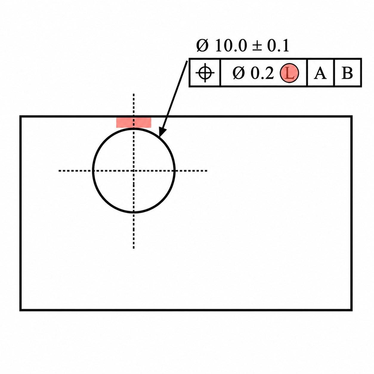
| LMC Ⓛ | The geometric tolerance is specified at LMC | Additional tolerance becomes available as the feature moves away from LMC | Features where minimum remaining material or wall thickness is important |
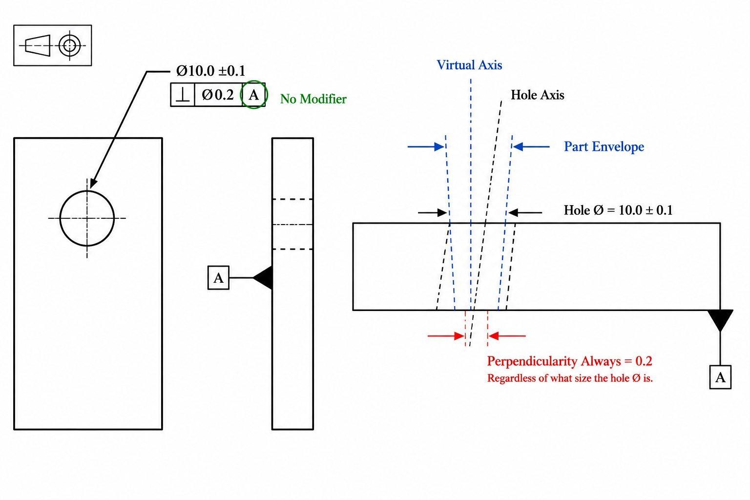
| RFS | The geometric tolerance is applied regardless of feature size | The stated geometric tolerance stays fixed | When feature location must be controlled independently of size |
MMC
MMC is commonly used when feature size and geometric location jointly affect assembly. For instance, consider a bolt hole. A smaller hole has less clearance around the bolt, so its position needs to be controlled more tightly. As the hole becomes larger, there is more room for the bolt even if the hole is slightly farther from its true position. MMC allows an increase in hole size to provide additional position tolerance.
LMC
LMC example (Machining Doctor)
LMC is useful when the concern is how much material remains around a feature. When LMC is specified, departure from LMC toward MMC can provide additional geometric tolerance in the same way that departure from MMC provides bonus tolerance under an MMC requirement.
For example, a hole located close to the edge of a component may need to maintain a minimum amount of material between the hole and the outside surface. In this situation, controlling the feature relative to its LMC condition can protect the required wall thickness.
MMC is commonly used for assembly-related requirements, while LMC can be useful when minimum remaining material is the functional concern.
RFS
Regardless of Feature Size (GD&T Basics)
RFS (Regardless of Feature Size) means that the geometric tolerance remains at the stated value regardless of the actual feature size. Under ASME Y14.5, RFS is the default condition when no MMC or LMC modifier is specified. For example, if a drawing specifies a position tolerance of ⌀0.20 mm at RFS, the position tolerance remains ⌀0.20 mm whether the hole is produced close to its MMC size or close to its opposite size limit.
This is useful when the location itself is the requirement and changing the feature size should not provide additional positional allowance.
Practical Difference
The choice depends on the functional requirement of the feature:
- MMC: Use when feature size and location jointly affect assembly.
- LMC: Use when maintaining minimum material or wall thickness is important.
- RFS: Use when the geometric tolerance should remain independent of feature size.
Common MMC Applications in Engineering Drawings
MMC is normally useful when feature size and feature location affect the same assembly. Hole patterns are a common example because the holes have to provide enough clearance for the mating fasteners while still staying within their positional limits.
MMC for Position Tolerance and Hole Patterns
MMC is commonly applied to hole patterns because hole size and position jointly affect assembly clearance. As a hole increases in size away from MMC, the resulting bonus tolerance can allow greater positional variation while maintaining the applicable functional boundary.
MMC for Functional Assembly
MMC is also useful for mating features whose size and location jointly determine assembly clearance. A locating pin and hole are a typical example: the worst assembly condition occurs when the pin is at its MMC size, and the hole is at its MMC size.
During inspection, the actual feature size matters. A hole that is larger than its MMC size has more available clearance, while a pin that is smaller than its MMC size has more available clearance. When the drawing applies MMC to the geometric tolerance, that size difference can be used as additional geometric tolerance.
It is especially helpful when a part needs to assemble reliably even though the manufactured features are not exactly at their nominal sizes.
How MMC Affects CNC Machining and Inspection
An MMC callout affects how the production and inspection team evaluates the feature's size and geometric tolerance. The feature must still meet its specified size limits, while the geometric requirement is evaluated according to the MMC modifier.
Machining Considerations for MMC-Controlled Features
For the machinist, the main concern is maintaining the feature size and its location within the drawing requirements.
For a CNC hole pattern, MMC requirements can affect the hole-making process, workholding strategy, program coordinates, and in-process size control. The process must maintain the hole within its size limits while keeping the feature location within the applicable geometric tolerance.
The important practical point is that holding the hole diameter alone is not enough. The hole pattern still needs to be produced in the correct location.
For an MMC-controlled hole pattern, the production process has to control both the hole size and the feature location relative to the specified datum reference frame. A larger hole may provide bonus positional tolerance, but it does not eliminate the requirement to meet the feature's size limits or other applicable drawing requirements.
For production runs, the machining process should also be monitored for tool wear and gradual size movement. As a hole-making tool wears, the hole diameter may drift away from its target size. Under an MMC-controlled position tolerance, that size change can affect the available bonus tolerance. Monitoring hole size during production is therefore important because tool wear can change the bonus tolerance available at inspection.
Inspection Methods for MMC Requirements
Inspection should follow the complete feature control frame, including the feature size limits, geometric tolerance, material condition modifier, and applicable datum reference frame. Checking the hole diameter alone does not establish whether an MMC-controlled position requirement has been satisfied.
For a hole pattern, inspection should establish the actual feature size and evaluate the hole location relative to the specified datum reference frame. When MMC is applied to the position tolerance, the measured departure from MMC determines the available bonus tolerance, which is then considered when evaluating the position result.
A CMM inspection can be used to measure feature size and location relative to the specified datum reference frame and evaluate the applicable geometric tolerance. For suitable production applications, a functional gauge can provide a fast pass/fail check of the feature's applicable functional boundary. However, a functional gauge does not replace dimensional or coordinate-based inspection when the drawing requires individual measurements or recorded inspection data.
CNC Manufacturing Note
In CNC production, an MMC-controlled hole pattern should not be managed by diameter alone. Hole size drift from tool wear changes the available bonus tolerance, while the positional requirement still has to be evaluated against the datum reference frame.
Common MMC Interpretation Mistakes
MMC is easy to misread when the feature size and the GD&T callout are looked at separately. The safest approach is to first identify the feature type and its size limits, then read the material condition modifier in the feature control frame.
Assuming MMC Means Maximum Size
MMC does not simply mean “the largest dimension.”
For a hole, MMC is the smallest allowed hole size because that condition leaves the most material around the hole.
For a shaft or pin, MMC is the largest allowed size because the larger feature contains more material.
The mistake usually happens when MMC is interpreted as a general “maximum size” requirement instead of a material condition.
Confusing MMC With RFS
MMC and RFS do not apply the geometric tolerance in the same way.
With MMC Ⓜ, the actual feature size can affect the amount of geometric tolerance available.
With RFS, the geometric tolerance remains at the value stated in the feature control frame, regardless of where the actual feature size falls within its size limits.
So when reading a drawing, check the modifier after the tolerance value rather than assuming that every position tolerance works under MMC.
Ignoring Bonus Tolerance
When MMC is specified, checking only the stated geometric tolerance can lead to an incorrect result. The actual feature size must also be considered because departure from MMC determines the available bonus tolerance.
Maximum Material Condition FAQs
Q: What is the maximum material condition in GD&T?
Maximum Material Condition (MMC) is the size condition in which a feature of size contains the maximum amount of material within its specified limits. For a hole, MMC is the smallest permitted size; for a shaft or pin, MMC is the largest permitted size.
Q: What is the MMC symbol in GD&T?
Look for Ⓜ in the feature control frame. Its position in the callout matters because it tells you which requirement is being modified. Do not treat the symbol as another size limit.
Q: How Do You Calculate MMC for a Hole or Shaft?
Use the feature's stated size limits, not its nominal dimension. For a hole, use the smaller limit. For a shaft or pin, use the larger limit. Once that value is identified, it can be used to evaluate the related MMC geometric requirement.
Q: What is bonus tolerance in MMC?
Bonus tolerance is the additional geometric tolerance available when a feature departs from MMC. For a hole, it equals the actual hole size minus the MMC size; for a shaft or pin, it equals the MMC size minus the actual size. On an inspection report, this means the measured feature size may need to be considered before deciding whether its position or other geometric characteristics pass.
Q: Does MMC Increase or Decrease Geometric Tolerance?
The stated geometric tolerance on the drawing does not change. However, the effective tolerance available to the manufactured feature can increase as the feature departs from MMC toward LMC. This is why the measured size matters during inspection.
Q: What is the difference between MMC and LMC?
The practical difference is the condition being protected. MMC is based on the feature containing the most material, while LMC is based on the least material. The designer selects between them according to the functional requirement of the feature.
Q: When should MMC be used in GD&T?
MMC is useful when the feature's size and geometric location work together in the assembly. A hole pattern is a common case: the hole size affects available clearance, while the position controls where that clearance is located. This makes MMC useful for connecting the drawing requirement to the actual assembly condition.
Q: How does MMC affect position tolerance?
When MMC is applied to a position tolerance, the stated tolerance applies at MMC. Each unit of departure from MMC provides an equivalent amount of bonus positional tolerance.
Precision CNC Machining Service
Professional manufacturing, fast turnaround, and quality assurance.
Conclusion About Maximum Material Condition
MMC is most useful when the size and location of a feature have to work together. It gives the drawing a way to control features such as holes and pins while allowing the geometric requirement to relate to the actual manufactured size.
When reviewing a drawing, check the feature size limits, Ⓜ modifier, geometric tolerance, and the functional requirement together. This is especially important for hole patterns and locating features where the final fit depends on both size and position.
For CNC parts with MMC-controlled features, JLCCNC can help review your drawing requirements and manufacture the part to the specified GD&T controls. Send your drawing or CAD file to discuss machining and inspection requirements.
Keep Learning
Circularity GD&T Explained
Key Takeaways Circularity controls how round each cross-section is on a cylindrical, conical, or spherical surface. Each cross-section is checked separately. Circularity doesn't control taper, axis straightness, or alignment between sections. No datum is needed because circularity controls the shape of the feature itself. The circularity tolerance zone is bounded by two concentric circles whose radial separation equals the specified tolerance. Each circular element must fit within its own zone, evalua......
Press Fit Tolerance: Interference, Charts & Design Guide
Key Takeaways A press fit is an interference fit: the shaft is larger than the hole, and elastic deformation of the mating parts after assembly creates contact pressure that generates the friction holding the joint together. Press fit interference is the difference between the shaft diameter and the hole diameter. Minimum interference uses worst-case dimensions for the smallest overlap. Maximum interference uses worst-case dimensions for the largest overlap. Press fit tolerance is selected based on re......
GD&T Datum: Definition, Types, Symbols, and Datum Reference Frame
Key Takeaways A datum in GD&T is a theoretically exact reference used to locate or orient other features on a part. It is not the physical surface itself. A datum feature is the physical feature identified on the part and used to establish a datum. The datum itself is the theoretically exact geometric reference derived from that feature. Datums become especially important when several features have to work together. A hole pattern, bearing bore, mounting face, or mating surface may need to establish t......
GD&T Runout: Definition, Symbol, Measurement & Tolerance
Key Takeaways Runout limits surface variation while a part rotates around its specified datum axis. The datum feature establishes the axis used for the runout requirement. You compare the full indicator variation during rotation with the tolerance stated on the drawing. Circular runout applies at individual circular sections of the controlled surface. Total runout evaluates the controlled surface across its specified extent. Runout is not a size tolerance, and its value is not determined by the diamet......
GD&T Perpendicularity: Definition, Tolerance & Examples
Key Takeaways Perpendicularity is an orientation control used for a feature specified at 90° to a datum. A surface callout controls the complete surface within two parallel planes set perpendicular to the referenced datum. An axis callout controls the derived axis inside the specified tolerance zone instead of controlling the physical surface directly. Perpendicularity does not establish the location of a feature. A drawing can require another geometric control when position also needs definition. Dat......
Concentricity in GD&T: Definition, Symbol, Tolerance, and Measurement
Key Takeaways Concentricity in legacy ASME GD&T controls the derived median points of a feature relative to a datum axis. It does not simply compare the axes of two fitted cylinders. Check the drawing standard first. Legacy ASME concentricity and ISO concentricity or coaxiality should not be interpreted as equivalent requirements. For the cylindrical example in this guide, the tolerance zone is a cylinder centered on the datum axis. The derived median points of the controlled feature must lie within t......