Sheet Metal Bending: Types, Process, Machines, and Materials
24 min
- What Is Sheet Metal Bending?
- How the Sheet Metal Bending Process Actually Works
- Sheet Metal Bending Types
- Sheet Metal Bending Machines
- Sheet Metal Bending Materials
- The Technical Factors That Actually Determine Bend Quality
- Advantages and Limitations
- Applications
- CNC Sheet Metal Bending
- Design Considerations for Sheet Metal Bending
- FAQs About Sheet Metal Bending
Key Takeaways
- Sheet metal bending causes permanent deformation by exceeding the material's yield strength along the bend line. Because the metal retains its structural continuity without thermal stresses, bent corners often offer superior fatigue strength compared to welded joints.
- The three sheet metal bending types that dominate production are air bending, bottoming, and coining, each making a different trade-off between flexibility and accuracy.
- Springback affects final bend angle and must be accounted for during process setup.
- Bend allowance and K-factor determine how long the flat blank needs to be before bending.
- CNC press brakes have become the standard sheet metal bending machine for precision multi-bend work, handling back gauge positioning and punch depth automatically from a programmed sequence.
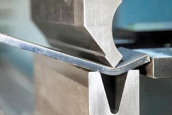
(Runsom) Sheet metal bending
Most sheet metal parts you see—including enclosures, brackets, panels, and channels—started life as a flat piece of metal. Sheet metal bending is what turned them into something three-dimensional. No material removed, no welding, no complicated tooling for each unique profile. Just controlled force applied in the right place, and the metal stays where you put it.
Simple in concept. Genuinely nuanced in practice. Springback, grain direction, bend allowance calculations, flange minimums, and sequence planning for complex parts all affect the result, so the process is worth understanding properly. Whether you're designing parts for bending or trying to understand why the shop floor keeps kicking your drawings back, this guide covers it all.
What Is Sheet Metal Bending?
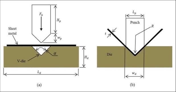
(ResearchGate) diagram of sheet metal bending
Sheet metal bending is a forming process that permanently deforms flat metal sheet into an angular shape by applying force along a straight bend line. Unlike machining, nothing gets cut away. Unlike welding, there's no join. The material is continuous from one side of the bend to the other, compressed on the inside, stretched on the outside, and it stays that way permanently once you exceed the yield strength.
That last point is important. Every material has two zones: elastic deformation, where the metal springs back after the load is removed, and plastic deformation, where it doesn't. Sheet metal bending works in the plastic zone. You need enough force to get there. If the applied force is insufficient, the metal bends temporarily and springs back when the load is removed.
What Happens Inside the Metal During Bending
Think about a cross-section through the bend. There's a line running through the thickness, the neutral axis, where the material is neither compressed nor stretched. On the inside of the bend, everything is in compression. On the outside, everything is in tension.
These two zones behave differently. The outer surface stretches and can crack if the strain becomes too high, which is why minimum bend radius is an important design consideration. The inner surface is subjected primarily to compressive strain, while the outer surface experiences tensile strain. Tensile strain is often the more critical condition for surface cracking during tight bends. What matters for the flat pattern calculation is that the neutral axis describes an arc when bent, and that arc length determines how much flat material you need before bending.
The neutral axis isn't exactly in the middle of the thickness. It shifts toward the inside of the bend. How far it shifts depends on the material, the bend radius relative to thickness, and the bending method. The K-factor is what quantifies this shift, and it's what makes the difference between a flat pattern that works and one that's consistently off.
Common Features Bending Produces
Flanges, channels, U-sections, box profiles, offsets, hems. All come from the same basic operation applied in different sequences. A simple L-bracket is one bend. An enclosure is four. A complex structural channel with return flanges might involve six or eight sequential operations on a press brake, each positioning the part differently against the back gauge.
Need Custom Sheet Metal Parts Bent?
JLCCNC provides custom sheet metal fabrication with laser cutting and bending for aluminum, stainless steel, cold-rolled steel, and galvanized steel. Parts are checked for manufacturing readiness against production standards.

Precision Sheet Metal Fabrication
Professional manufacturing, fast turnaround, and quality assurance.
How the Sheet Metal Bending Process Actually Works
Prepare the Sheet Metal
It starts with a flat blank, either cut from stock sheet or, more commonly in modern fabrication, laser-cut with all holes and cutouts already in place. Here’s a guide to sheet metal cutting methods, accuracy, and the factors that affect cut quality before the part reaches the press brake. Sheet Metal Cutting Guide.
The flat pattern dimensions must already account for bend allowance at every bend. This is not something to figure out later. Get the flat dimensions wrong and every part in the run will have the wrong dimensions after bending.
Check cut edges for burrs before bending. Burrs that sit against the die surface prevent the sheet from seating flat, which produces inconsistent bend angles. A quick deburr pass saves a lot of trouble. You can check our sheet metal deburring guide for that.
Select the Tooling and Die
The die opening width is the critical selection. For many air-bending setups, the inside bend radius can be estimated from the V-die opening using a shop-specific rule of thumb, often around V/6 for certain materials and setups. Actual results depend on material, thickness, tooling, and bending conditions. Die opening should be selected based on material thickness, required bend radius, flange geometry, and machine capacity.
Punch profile selection depends on the geometry. Standard punches handle most work. Gooseneck punches clear previously formed flanges in complex multi-bend parts. Radius punches produce smooth curves instead of sharp bends. Hemming punches are used to form folded or closed edges.
Apply the Bending Force
The punch descends. It contacts the sheet surface and drives it into the die. Depending on the bending method—air bending, bottoming, or coining—the punch stops at a different position during its stroke. The force required depends on material strength, thickness, bend length, and die opening width.
Bending force is commonly estimated from material strength, thickness, bend length, and die opening. Use the press brake manufacturer's force chart or a validated calculation for the selected tooling and material.
Inspect the Finished Bend
The first article is checked for bend angle, flange lengths, and overall dimensions. If the angle is off, the springback compensation is adjusted before running the batch. Dimensional measurements confirm the flat pattern was correct. For tight-tolerance work, a CMM takes over from hand measurement.
Sheet Metal Bending Types
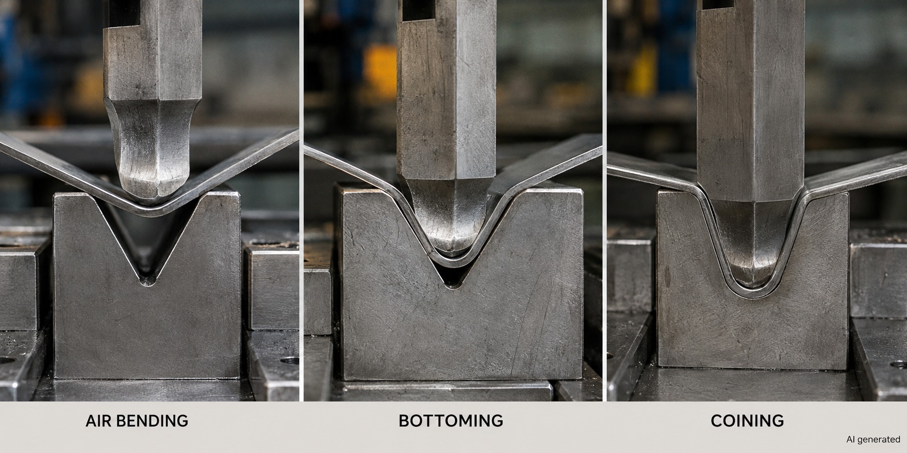
Air Bending, Bottoming, and Coining
| Method | Tooling Contact | Accuracy | Springback | Flexibility | Best For |
|---|---|---|---|---|---|
| Air Bending | Partial, 3-point contact | Moderate | Significant | High, many angles, one die | General fabrication, prototype |
| Bottoming | Full die contact | High | Low | Moderate | Production parts, precise angles |
| Coining | Penetrating | Very High | None | Low | High precision, small radius |
| U-Bending | Full U-die | Moderate | Moderate | Low | Channels, U-profiles |
| Roll Bending | Continuous roll contact | Moderate | Low | High | Tubes, cones, large radius |
| Wipe Bending | Wipe die face | Moderate | Moderate | Moderate | Edge flanges |
Air Bending
Air bending accounts for the majority of sheet metal bending operations in modern fabrication, somewhere around 90% alongside bottoming. The punch applies force to the sheet and drives it against or between the selected tooling. The required force depends on material strength, thickness, bend length, tooling geometry, and bending method.
That's the key thing about air bending: one 90° die can produce bends anywhere from just under 90° to 180°, just by varying how far the punch descends. No die change for different angles. For shops running varied work across short runs, this flexibility is enormously valuable, you're not swapping tooling between every job.
The trade-off is greater springback. Because the material is not pressed fully against the die, the final angle can deviate more after the punch retracts. The standard approach is to overbend by the springback amount, bend to 87° if you want 90° after springback, for example. Getting this right requires either a first-part trial or very good material characterization.
Bottoming
Bottoming presses the sheet fully onto the die surface. The die angle now determines the final part angle directly, unlike air bending where punch depth does the job. This closer relationship between tooling geometry and part geometry reduces springback substantially, which is why bottoming produces more consistent angles across a production run.
The trade-off is tooling specificity. A 90° die and a 120° die are different tools. If your part has both angles, you need both dies, whereas air bending handles both with the same V-die at different depth settings. For high-volume production of parts with consistent angles, bottoming's accuracy advantage outweighs the tooling commitment. For varied short-run work, air bending wins on flexibility.
Coining
Coining is where things get serious. The punch drives the material hard enough that it penetrates slightly into the sheet surface, deforming the material so completely that elastic springback is essentially zero. Coining can produce highly consistent bend angles when the tooling, material, and machine conditions are well controlled.
The trade-off is significantly higher force requirements. Coining can require several times the force of air bending for comparable material and thickness. You need the right machine capacity, the right die, and a compelling reason to need this level of precision. For most fabrication work, bottoming or carefully calibrated air bending is sufficient. Coining is for the applications where it absolutely has to be right every time, with no variation.
U-Bending
U-bending uses a U-shaped punch and die to produce a U-section profile in one operation. It is less flexible than V-bending for general work but can be efficient for high-volume production of the same channel profile. Standard U-sections can also be produced by two sequential V-bends, which gives you more flexibility in radius and flange length without committing to a fixed U-die.
Roll Bending
Roll bending is a different category from press braking. Instead of angular bends, you get continuous curves, tubes, cones, cylindrical sections, large-radius curved panels. The sheet passes through three rolls, typically with two drive rolls and one adjustable forming roll. The forming roll position controls the resulting radius. Tighter forming roll position produces a tighter curve.
One limitation of roll bending is that the sheet ends typically remain flat. The last few centimeters of each end don't make full contact with the forming roll, leaving a straight section at each end of the formed part. If you need curves right to the edge, those ends need a separate press brake operation first.
Wipe Bending
The sheet clamps against the wipe die, and the punch wipes down along the die face to form the flange. The die face determines the inside radius. It's a simpler process often found in automated fabrication lines for producing consistent edge flanges, but edge quality isn't quite as controlled as press brake bending with matched tooling.
Sheet Metal Bending Machines
Press Brake
The press brake is the workhorse of sheet metal bending. A rigid frame, a hydraulically or electrically driven ram carrying the punch, a fixed bed with the die, and a back gauge system. Press brakes are rated by tonnage (maximum force) and bed length, a 100-tonne, 3-meter machine covers the majority of general fabrication work.
The punch and die don't touch each other in normal operation. They're separated by the material being bent, and the space between them when the punch is at bottom determines the final bend geometry.
CNC Press Brake
A CNC press brake uses programmed ram movement and back gauge positioning to automate bend sequences. It is particularly useful for parts with multiple bends, different flange lengths, or tight dimensional requirements.
This is what makes complex multi-bend parts practical in production. Without CNC, every bend requires the operator to manually adjust the back gauge, manually judge the punch depth, and manually check the angle. With CNC, those decisions are made once during programming and executed identically on every part. First-article inspection still happens, and the program gets fine-tuned based on the results. After that, the machine just runs.
Worth mentioning separately because they're genuinely important. The back gauge is a CNC-controlled stop that positions the sheet for each bend. On complex multi-bend parts, the back gauge repositions between every operation, automatically, consistently, within fractions of a millimeter. It's the component that makes dimensional repeatability across production runs possible.
Hydraulic Press Brake
Most high-capacity press brakes are hydraulic, hydraulic cylinders provide the force, and the system is well-suited to the sustained high forces needed for thick material. Modern hydraulic machines incorporate CNC control of the hydraulic system for precise positioning. Hydraulic press brakes can provide high force throughout the stroke. This is useful for long bend lines where force requirements can vary as the sheet engages the die.
Roll Bending Machine
Separate machine category from press brakes, three rolls (typically), powered drive rolls, and an adjustable forming roll whose position controls the bend radius. CNC control programs radius and can vary it along the part length for complex curved profiles. Used for tubes, cones, curved structural members, and large-radius profiles that a press brake can't produce in a single operation.
Sheet Metal Bending Materials
| Material | Relative Bending Force | Minimum Radius Guide | Key Consideration |
|---|---|---|---|
| Mild Steel | 1× (baseline) | = Material thickness | Most forgiving, widest process window |
| Stainless Steel | ~1.7× | 1-2× Material thickness | Work hardens; needs more force than expected |
| Aluminum (soft) | ~0.5× | = Material thickness | Grain direction critical; avoid bending parallel to rolling |
| Aluminum (6061-T6) | ~0.65× | 2-3× Material thickness | Limited ductility; cracks at tight radii |
| Copper | ~0.5× | <Material thickness possible | Very ductile; easy to form |
| Brass | ~0.5× | = Material thickness | Good workability; mark protection on visible faces |
| Galvanized Steel | ~1× | = Material thickness | Zinc coating can crack at tight radii |
Aluminum
Works well for sheet metal bending and needs about half the force of steel. Aluminum alloy and temper strongly affect bendability. Harder tempers such as 6061-T6 generally require larger bend radii and more careful control than softer aluminum tempers. Bending parallel to the rolling direction can increase cracking risk in some aluminum alloys and tempers, particularly at tight bend radii. Bending perpendicular to the rolling direction crosses the grain fibers rather than splitting along them, and produces reliably better results.
With 6061-T6 specifically, minimum bend radius needs real respect. It has limited ductility in T6 temper and cracks at radii that softer aluminum alloys would handle without complaint. Check the material specification for the specific alloy and temper before committing to a tight radius.
Stainless Steel
More force, better precision requirements, more attention to surface. Stainless steel generally requires more bending force than mild steel, with the actual ratio depending on grade, thickness, tooling, and material strength. Austenitic grades like 304 and 316 work-harden as they're bent, the material gets harder through the operation, which affects both tooling wear and springback behavior. Brushed or polished surfaces need protection during bending because die contact marks visible surfaces.
Mild Steel
The reference material. Bending force charts are built around it. Most forgiving of all common sheet metal bending materials, reasonable ductility, predictable springback, wide process window. If you're learning press brake operation or dialing in a new setup, start here.
Copper and Brass
Both bend beautifully. Copper is highly ductile and can often accommodate relatively tight bend radii, depending on grade, temper, thickness, and surface condition. The main practical consideration for finished parts is surface marking, die contact leaves marks on soft copper and brass surfaces that matter for visible components. Soft-faced tooling or protective film solves this.
The Technical Factors That Actually Determine Bend Quality
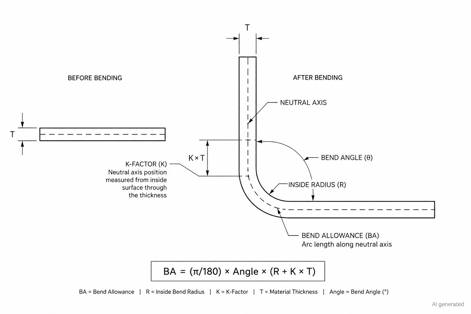
Bend allowance & K-factor diagram
Springback
You can't avoid it, so you have to compensate for it. After the bending force releases, the elastic portion of the deformation recovers. The part springs back by some amount, how much depends on the material's yield strength relative to its elastic modulus, the bend radius, the material thickness, and the bending method.
Higher strength materials spring back more. Larger inside radii spring back more than tight ones. Air bending springs back more than bottoming, which springs back more than coining.
The practical compensation: overbend, then let it spring back to the target angle. Getting the compensation amount right requires either a first-part trial and measure approach (most common in production), or sophisticated material modeling. Shops with consistent material supply and established processes develop reliable compensation values from experience. When material changes supplier or batch, those values may need re-verification.
Bend Allowance and K-Factor
This is the calculation that determines how long your flat blank needs to be. When a sheet is bent, the neutral axis describes an arc. That arc is longer than the inside of the bend and shorter than the outside. The flat blank needs to account for this arc length, the bend allowance, at every bend.
The K-factor tells you where the neutral axis sits. K = 0.5 means it's in the exact middle of the thickness. In practice it's usually between 0.3 and 0.45 for common materials in air bending, shifting the neutral axis slightly toward the inside of the bend.
Bend allowance formula for bends up to 90°:
BA = (π/180) × angle × (inside radius + K × thickness)
If you're using CAD software with a proper sheet metal environment, it handles this automatically, that's literally what that environment is for. If you're producing flat patterns manually, use a K-factor table calibrated to your material and process rather than guessing. A wrong K-factor means every part in the run is wrong in exactly the same way.
Grain Direction
The rolling process that creates sheet metal produces a directional grain structure. Bending behavior differs depending on whether the bend line runs parallel or perpendicular to this grain. Perpendicular bending (bend line crosses the grain) distributes the elongation across more grain boundaries and consistently produces better results. Parallel bending runs the risk of splitting along the grain, especially in harder materials, higher-strength alloys, and at tight bend radii.
Design bend lines to cross the grain wherever the part geometry allows. For parts where all four sides need bending, a box enclosure, for example, you'll inevitably have two bends parallel to the grain. Use radius values that give you margin on those bends.
Die Opening and Its Downstream Effects
The V-die opening width controls more than most people realize. In air bending, it determines the achievable inside radius (approximately V/6). It determines the minimum flange length (the sheet needs to bridge the die opening, too short a flange and it falls in). It determines the required bending force (wider opening needs less force but produces a larger radius). These relationships mean die selection is not just about choosing the right angle. The opening width also affects the bend radius, flange length, and required force.
A poorly cut blank can create problems that only become obvious during forming, from distorted edges to dimensional errors and burrs. Here’s a guide to 9 common sheet metal cutting problems and how to troubleshoot them before they affect downstream fabrication. 9 Sheet Metal Cutting Problems and Solutions
Advantages and Limitations
Why Bending Is Often the Right Answer
No material is removed during bending. The sheet remains continuous through the bend, which can avoid some of the strength and distortion issues associated with welded joints. There's no heat input distorting the material, no filler material with different properties, no potential porosity at the joint.
Production efficiency can be high once the tooling and process are established. CNC press brakes can efficiently produce multi-bend parts once the process is programmed and set up. Changeover between different parts is fast, back gauge program, maybe a die swap. Material utilization is good because flat blanks nest efficiently on a sheet with minimal waste between profiles.
Where It Falls Short
Geometry is constrained. If the part can't be unfolded into a flat pattern, it can't be bent. Complex 3D curvatures, undercuts, and geometries that would require the material to simultaneously deform in multiple directions need different processes, deep drawing, hydroforming, stamping.
Minimum flange length is a real constraint that catches designers out. If the flange is too short, it may not remain properly supported during bending. Sometimes the right answer is to redesign the part; sometimes it's to add a longer flange and trim it after bending.
Springback adds process complexity, particularly with high-strength materials. Getting consistent angles in very high-strength steel requires either coining (high force) or extremely well-characterized air bending process with reliable springback data.
Applications
| Application | Typical Geometry | Why Bending |
|---|---|---|
| Electrical enclosures | Box sections, flanged panels | One-piece, strong, sealed corners |
| Brackets and mounts | L-sections, Z-sections, channels | Structural stiffness from geometry |
| Automotive body structure | Complex multi-bend sections | Weight-efficient structural profiles |
| Bus bars and cable trays | Formed copper/aluminum profiles | Continuous cross-section, no joint resistance |
| Industrial guards and housings | Panel and channel sections | Fast production, good surface |
| Aerospace ribs and brackets | Precise multi-bend aluminum | Material-efficient, no machining waste |
CNC Sheet Metal Bending
CNC press brakes changed what's practically achievable in sheet metal bending for complex parts. Before CNC, producing a part with six sequential bends at different angles and different flange lengths meant six separate manual setups, each one an opportunity for the operator to position the back gauge slightly differently, apply slightly different force, get a slightly different result.
CNC bending is particularly valuable for multi-bend production because the bend sequence, workpiece positioning, and machine settings can be programmed in advance. Offline programming can also simulate tooling access and potential collisions before production. First-article inspection is still required to verify the programmed process against the actual material and machine setup.
For prototypes and low-volume work, this is genuinely fast. A new part program takes hours, not days. First article gets checked and adjusted same day. For production, the repeatability means you're not spending time measuring angles between parts, you measure periodically for process control, not continuously to compensate for drift.
Angle tolerances around ±0.5° may be achievable on well-maintained CNC press brakes with appropriate tooling, material control, and process setup. Where ISO 2768 is specified on the drawing, applicable general tolerances can provide a baseline for linear dimensions when individual tolerances are not given.
Design Considerations for Sheet Metal Bending
Minimum Bend Radius
A starting point for many common sheet-metal materials is an inside bend radius around the material thickness. The appropriate minimum radius still depends on alloy, temper, thickness, grain direction, tooling, and bend method. Going tighter than this is possible in ductile materials, copper, soft aluminum, but needs verification in the specific material and temper. Never assume a tight radius will work in a high-strength alloy without checking.
Keep Holes Away from Bend Lines
Keep holes and slots far enough from the bend zone to prevent distortion. A common starting rule is to place the feature edge at least the material thickness plus the inside bend radius from the bend line, then verify the distance against the material and tooling. Slots and notches close to bends are worse, stress concentrations at the feature corners can cause tearing. Move features away from bend lines wherever the design allows.
Bend Reliefs
Where a bend line meets a perpendicular edge or feature, add a bend relief. Without it, the material at the transition has nowhere to go and either tears or deforms badly into the adjacent geometry. Relief dimensions should be sized according to material thickness, bend radius, tooling, and the geometry of the adjoining feature. As a starting point, the relief should provide enough clearance for the material to deform without tearing or distorting the adjacent edge. Add a small radius at the inside corners of the relief to reduce stress concentration. This is one of those things experienced designers do automatically because they've seen what happens without it.
These details become especially important when several bends, holes, flanges, and mounting features have to work together in the same part. Here’s a guide to sheet metal enclosure design, including material, thickness, and manufacturing considerations. Sheet Metal Enclosure Design Guide
Minimum Flange Length
The minimum achievable flange length in air bending is approximately half the die opening width, the sheet needs to bridge across the V and have enough length to stay supported. As a practical rule, keep flanges at least 4× material thickness long, and check against the bending force chart for the specific die opening being used. Short flanges on large heavy parts cause particular difficulties, manual handling may be needed to support the part during bending, which adds cost.
Think About Bend Sequence Early
For parts with multiple bends, plan the sequence before finalizing the design. Each successive bend must be achievable without the geometry from previous bends interfering with tool access or back gauge clearance. On simple parts this is intuitive. On complex parts with return flanges and closely spaced bends facing different directions, it genuinely needs to be thought through. Offline programming software simulates the sequence and catches collisions, but if you're designing without it, run through the sequence mentally at the design stage.
Near-Symmetrical Parts
This sounds trivial but it causes real problems on the shop floor. A nearly symmetrical bracket can be easy to orient incorrectly, especially when reversing the bend produces a mirror image of the intended part. If it can be made symmetric without affecting function, make it symmetric. If it can't, make the asymmetry obvious: a clearly offset hole, a different flange length, a visible marking. Don't leave the operator guessing which way the bend goes.
The right bending method, material, tooling, and bend geometry can make a big difference in the finished part. If you already have a design, JLCCNC can handle the sheet metal fabrication process from laser cutting to bending, with support for common materials and production thicknesses from 0.5 to 6 mm.
Upload your design to JLCCNC and get a quote for custom sheet metal parts.
Precision Sheet Metal Fabrication
Professional manufacturing, fast turnaround, and quality assurance.
FAQs About Sheet Metal Bending
Q: What is sheet metal bending?
Sheet metal bending is a forming process that permanently deforms flat metal sheet into angular geometry by applying force that exceeds the material's yield strength along a controlled bend line. No material is removed, the sheet is compressed on the inside of the bend and stretched on the outside, creating a rigid three-dimensional shape from flat stock. Common applications include enclosures, brackets, channels, and structural sections across virtually every industry that uses fabricated metal.
Q: What are the different types of sheet metal bending?
The main sheet metal bending types are air bending (most common, punch doesn't fully contact die, angle controlled by punch depth, significant springback), bottoming (punch presses sheet fully onto die, more accurate, less springback), and coining (highest accuracy, essentially no springback, requires 5-8× the force of air bending). Other sheet metal bending methods include U-bending for channel profiles, roll bending for continuous curves, and wipe bending for simple edge flanges.
Q: What machine is used for sheet metal bending?
The press brake is the primary sheet metal bending machine, available in manual, hydraulic, and CNC configurations. CNC press brakes dominate modern precision fabrication, controlling punch depth and back gauge position automatically from a programmed sequence. Roll bending machines produce continuous curves rather than angular bends and are a separate machine category from press brakes.
Q: What materials can be bent?
Mild steel, stainless steel, aluminum, galvanized steel, copper, and brass are all common sheet metal bending materials. Each has different force requirements and minimum bend radius considerations. Mild steel is the most forgiving. Stainless needs about 1.7× more force than mild steel. Aluminum in harder tempers like 6061-T6 has limited ductility and cracks at tight radii.
Q: What is the minimum bend radius?
There is no single minimum bend radius for all sheet metal. As a starting point, an inside radius near the material thickness may work for many common materials, but the required radius depends on alloy, temper, thickness, grain direction, and bending method.
Popular Articles
• 9 Sheet Metal Cutting Problems and Solutions
• Hole cutting in sheet metal: techniques, tolerances and applications
• Introduction to Sheet Metal Processing: Techniques and Tools for Precision
• Bending and Forming Technology in Sheet Metal Processing
• Laser cutting technology in sheet metal processing
Keep Learning
Galvanized Sheet Metal: Grades, Specs & When to Use It
Galvanized Sheet Metal: Grades, Specs & When to Use It A design engineer specs "galvanized sheet metal" on a drawing and sends it out for quotes. Three shops come back with three different prices, and one of them asks a follow-up question the others didn't: which gauge, which coating class, hot-dip or electro-galvanized? That question is the difference between a part that survives outdoors for fifteen years and one that starts showing rust spots after eighteen months — and it's the kind of detail that......
Custom Sheet Metal Fabrication: How the Process Works From Design to Delivery
Custom Sheet Metal Fabrication: How the Process Works From Design to Delivery A stock enclosure almost fits. The mounting holes are close but not quite right, the depth is half an inch too shallow, and the vendor's next size up is twice the volume you actually need. This is the point where most people start looking into custom sheet metal fabrication — not because they set out to design a part from scratch, but because nothing off the shelf actually solves the problem. Custom fabrication sounds like i......
Sheet Metal Assembly: How Fabricated Parts Come Together
Sheet Metal Assembly: How Fabricated Parts Come Together Cutting and bending gets a lot of attention because that's where a flat sheet visibly turns into a 3D part. But a single bracket by itself rarely finishes the job — most real sheet metal products are assemblies, multiple formed pieces joined into one working unit, and that assembly step is where a lot of designs quietly succeed or fail. A part that measured perfectly on its own can still not fit once it's supposed to mate with three other pieces......
Sheet Metal Bender: Types, Specs & How to Choose the Right Machine
Sheet Metal Bender: Types, Specs & How to Choose the Right Machine Every sheet metal bracket, enclosure, and panel eventually passes through a bender of some kind — that's the machine, not the process. Our guide on sheet metal bending covers how bending actually deforms metal — springback, minimum radius, bend allowance, and the core press brake and CNC press brake setups most shops run. This one goes further into the equipment side specifically: the less common bender types beyond the standard press ......
What Is Galvanized Metal? Process, Types & How It Works
What Is Galvanized Metal? Process, Types & How It Works Leave a piece of bare steel outside for a season and you'll see exactly why galvanizing exists. Rust doesn't wait for dramatic weather — a little humidity and a few weeks is enough to start eating into an unprotected surface. Galvanized metal solves that problem by giving steel a sacrificial layer of zinc that corrodes in its place, and it's done this job well enough that it's become the default choice for anything from highway guardrails to HVAC......
What Is Sheet Metal Fabrication? The Complete Guide
What Is Sheet Metal Fabrication? The Complete Guide Somewhere between a CAD file and a working enclosure sitting on your bench, a flat piece of metal gets cut, bent, joined, and finished into something that actually does a job. That's sheet metal fabrication — and if you've never ordered a part before, the term can feel bigger than it needs to be. Ask five people what "sheet metal fabrication" covers and you'll get five different answers: some think laser cutting, some think welding, some just picture......