How to Read Surface Roughness Symbols: Drawing Examples & ISO Guide
19 min
- What Is a Surface Roughness Symbol?
- Understanding Surface Roughness Symbols
- How to Read Surface Roughness Symbols on Drawings
- Common Surface Roughness Symbol Examples
- Surface Roughness Symbol Standards
- How to Specify Surface Roughness Symbols Correctly
- Common Mistakes When Using Surface Roughness Symbols
- Best Practices for Surface Finish Drawings
- FAQs About Surface Roughness Symbols
Key Takeaways
- Surface roughness symbols define the required finish for individual features on an engineering drawing.
- ISO 1302 provides the standard symbols used on most international technical drawings.
- A surface finish callout can include the roughness value, machining requirement, lay direction, and supplementary notes.
- Ra is the roughness parameter specified most frequently, although Rz is common for some functional surfaces.
- Correct interpretation of a callout helps match the surface requirement with an appropriate manufacturing process.
- Specifying finer finishes than necessary increases machining, inspection, and production costs.
Surface finish requirements are easy to overlook on an engineering drawing. Although they often determine the final machining operation before a part leaves the shop, they may receive less attention than dimensions or tolerances during drawing review. Two faces on the same component may share identical dimensions, but only one requires grinding, polishing, or another finishing process. That difference is communicated through a surface roughness symbol.
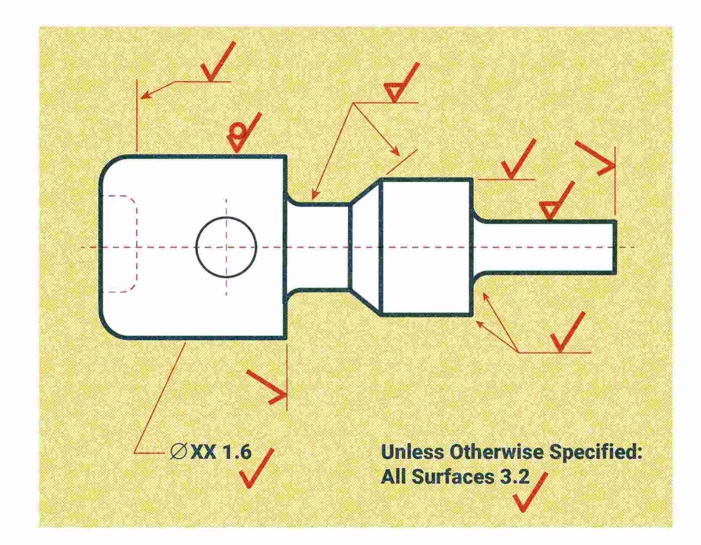
Surface Texture/Finish (Open Washington Pressbooks)
Take a shaft as an example. The bearing seat usually needs a much finer finish than the remaining diameter because both surfaces perform different functions after assembly. If the drawing is interpreted incorrectly, the part may need additional machining, fail inspection, or require unnecessary rework before delivery.
This article will walk you through:
- The purpose of surface roughness symbols on engineering drawings.
- The elements included in a standard surface finish callout.
- The meaning of ISO 1302 symbols and common roughness parameters.
- Practical examples of surface roughness symbols used in milling, turning, and grinding drawings.
- The differences between ISO and ASME surface finish standards.
- Good practices for specifying and interpreting surface finish requirements.
- Common mistakes that can lead to machining or inspection problems.
What Is a Surface Roughness Symbol?
Surface Roughness Symbol (WisTech Open)
A surface roughness symbol is a standardized symbol on an engineering drawing that specifies the required surface finish for a particular feature. It tells the manufacturer the surface quality that must be achieved after machining or another finishing operation.
Dimensions define the size of a feature, but they do not describe its surface condition. A surface roughness symbol fills that gap by identifying which surfaces require a specific finish. For example, a bearing seat, sealing face, and mounting surface on the same part may each have different finish requirements based on their function.
Surface Roughness Symbols vs Surface Texture Symbols
Graphical symbol for surface texture (ResearchGate)
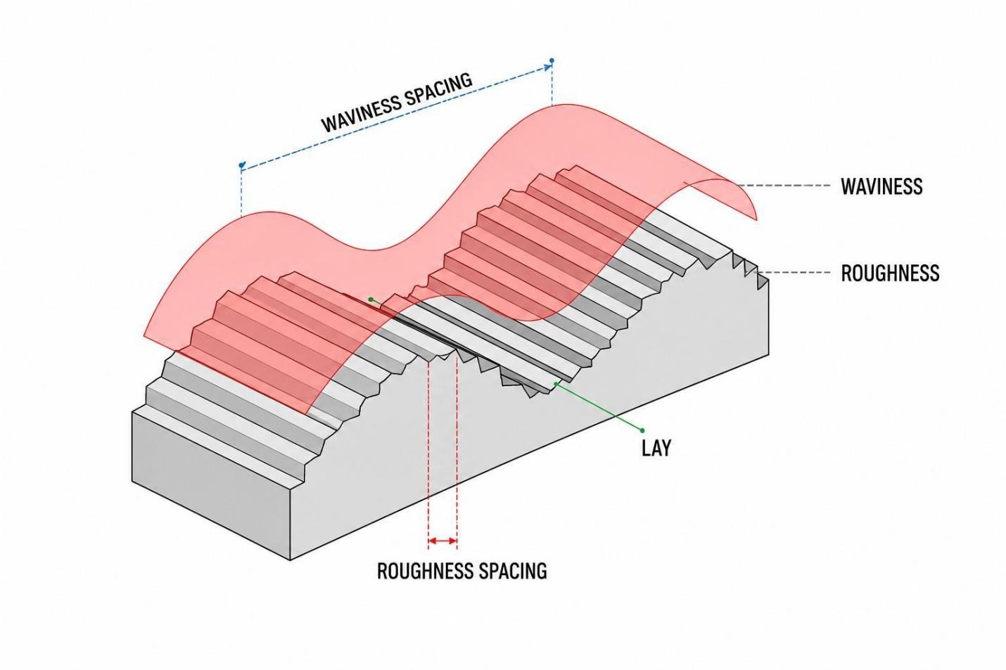
Many engineers use these two terms interchangeably during everyday discussions. On engineering drawings, however, surface roughness represents only one part of the overall surface texture specification. Surface texture can include additional information beyond the roughness value, depending on the drawing requirements.
Although the term "surface roughness symbol" is widely used in industry, ISO 1302 formally defines these markings as surface texture symbols because they may specify more than roughness alone.
Although many engineers often refer to every ISO 1302 callout as a surface roughness symbol, the completed symbol can communicate much more than the finish value alone.
| Feature | Surface Roughness Symbol | Surface Texture Symbol |
|---|---|---|
| Primary purpose | Specifies the required roughness value. | Defines the complete surface texture requirement. |
| Scope | Covers surface roughness only. | Covers roughness, waviness, lay, and supplementary surface information. |
| Standard | Uses ISO 1302 roughness notation. | Uses ISO 1302 with additional surface texture elements. |
| Parameters | Ra, Rz, Rq, Rt, Rmax. | Roughness parameters together with lay direction, machining allowance, cutoff length, and process notes. |
| Manufacturing guidance | Defines the required surface finish. | Defines the complete surface specification for manufacturing. |
| Inspection | Verifies the specified roughness parameter. | May include roughness, lay, waviness, and other texture characteristics. |
| Typical applications | Bearing seats, shafts, sealing faces, sliding surfaces. | Aerospace components, molds, medical devices, optical parts, and precision tooling. |
| Information level | Focused on roughness requirements. | Covers multiple surface characteristics in one specification. |
Why Surface Finish Symbols Are Used
Surface finish symbols specify the required surface condition for individual features on an engineering drawing. They help ensure functional surfaces receive the correct machining or finishing process while avoiding unnecessary work on non-critical areas.
The primary purposes of surface finish symbols include:
- Show which surfaces require a specified surface finish.
- Help machinists select the appropriate machining or finishing process.
- Identify features that require grinding, polishing, lapping, or other secondary operations.
- Guide inspectors when verifying surface finish against drawing specifications.
- Prevent unnecessary finishing on surfaces that do not affect part function or assembly.
Understanding Surface Roughness Symbols
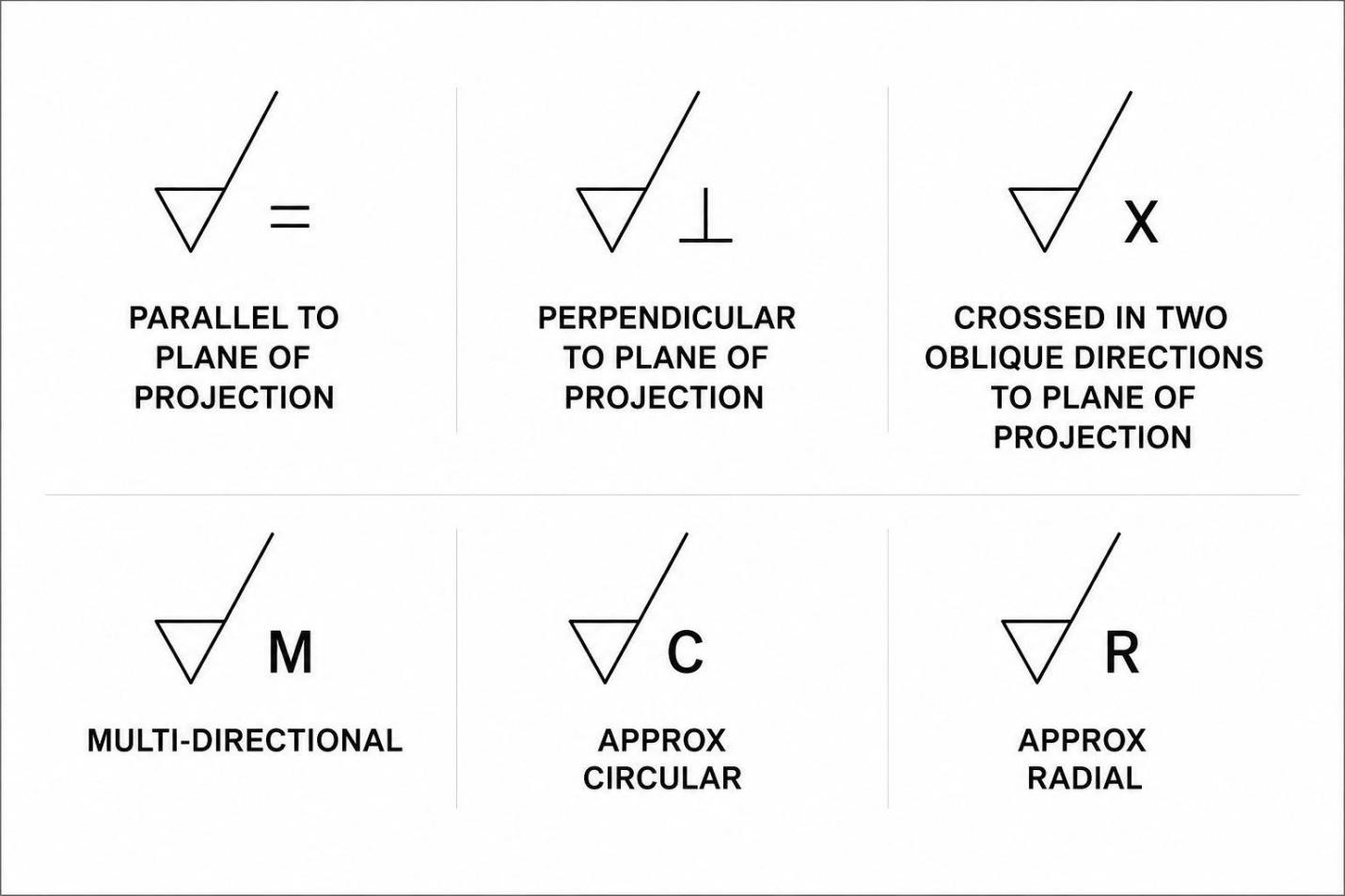
Surface Finish Symbols and Texture Indications (RoyMech)
A surface roughness symbol conveys more than a finish value. Each part of the symbol provides manufacturing instructions that helps machinists produce the required surface and helps inspectors verify the finished part.
The Basic Surface Finish Symbol
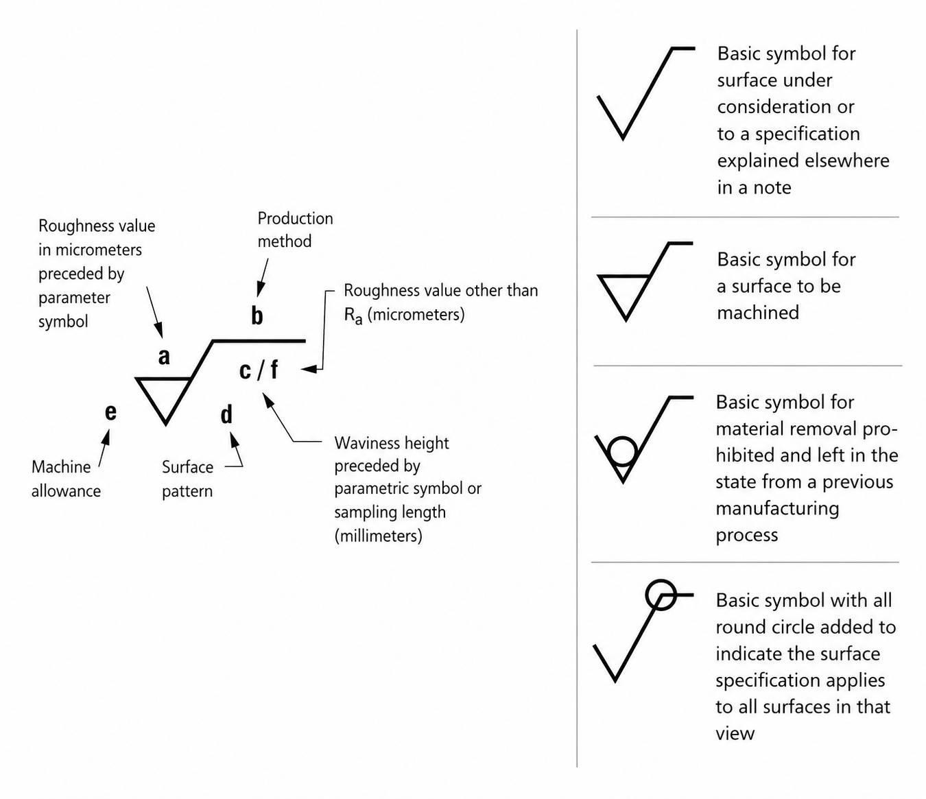
ISO surface roughness symbol (Autodesk Community)
The basic surface finish symbol is the foundation of every ISO 1302 surface finish callout. By itself, it only indicates that a surface finish requirement exists. Additional information is added to define the required surface condition.
The basic surface finish symbol is used to:
- Indicate that a surface has a specified finish requirement.
- Define the required roughness value when additional data is included.
- Show whether material removal is required or prohibited.
- Identify the surfaces that require controlled finishing.
- Apply surface finish requirements to individual features or the entire drawing.
- Provide a consistent method for communicating finish requirements during manufacturing and inspection.
Material Removal Indicators
Small changes to the basic symbol communicate whether machining is required after the initial manufacturing process. These indicators help production teams select the correct finishing operation before the part reaches inspection.
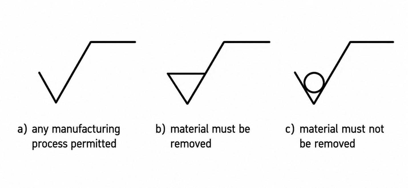
Basic symbol: Indicates a surface finish requirement without specifying whether material removal is required.
Bar added to the symbol: The surface shall be produced by material removal. The surface must be produced through machining, grinding, polishing, or another material removal process.
Circle added to the symbol: Material removal is not permitted. The surface must remain in its original condition after casting, forging, additive manufacturing, or another primary process.
Designers prohibit material removal when preserving the original manufactured surface is functionally important.
Selecting the correct indicator prevents unnecessary machining and ensures the manufacturing process matches the design intent.
Surface Roughness Values and Parameters
The roughness value tells the manufacturer how smooth the finished surface should be. On most engineering drawings, this value appears above the symbol and is typically expressed in micrometers (um) using the Ra parameter.
Although Ra appears on most engineering drawings, designers select other parameters whenever the application requires additional control over the surface profile. If you need a broader comparison of Ra, Rz, surface finish grades, achievable machining values, and process capabilities, see the surface roughness guide.
Choosing the correct roughness value depends on the function of the surface as well as the manufacturing process used to produce it. During quotation, JLCCNC reviews surface finish requirements together with part geometry to identify specifications that may increase machining cost or require additional finishing operations. Upload your engineering drawing to receive a CNC machining quote and engineering review.
| Parameter | Description | Common Applications |
|---|---|---|
| Ra | Arithmetic average roughness. The most widely specified parameter. | General CNC machining, shafts, housings, sealing faces |
| Rz | Average height difference between the highest peaks and deepest valleys. | Gaskets, sealing surfaces, functional contact areas |
| Rq | Root mean square roughness. Gives greater influence to larger surface variations. | Precision engineering and research applications |
| Rt | Total height from the highest peak to the deepest valley within the evaluation length. | Surface evaluation requiring maximum profile height |
| Rmax | Maximum single roughness depth measured within the sampling length. | Specialized inspection and quality verification |

Precision CNC Machining Service
Professional manufacturing, fast turnaround, and quality assurance.
Supplementary Symbol Elements
Surface roughness symbols can include extra information that guides both manufacturing and inspection. These details become useful whenever the roughness value alone cannot fully describe the required surface.
Common supplementary elements include:
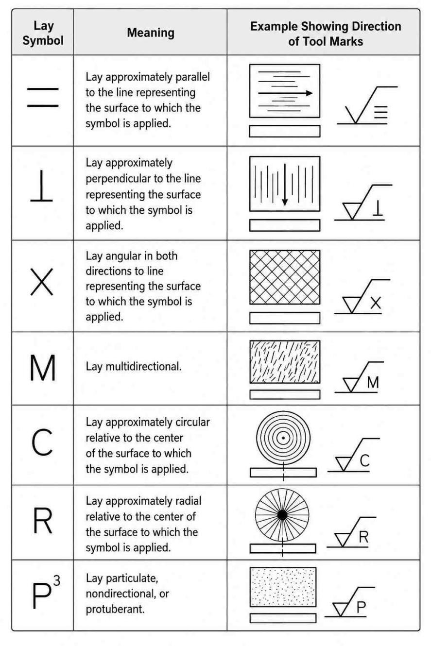
- Manufacturing method: Specifies processes such as grinding, milling, turning, polishing, honing, or lapping.
- Lay direction: Defines the direction of machining marks relative to the surface.
- Machining allowance: Indicates the amount of material left for a finishing operation.
- Sampling (cutoff) length: Defines the evaluation length used during roughness measurement.
- Surface treatment notes: Adds instructions for coating, plating, anodizing, bead blasting, or other finishing operations when required.
- Special inspection notes: Provides additional measurement or verification requirements for critical surfaces.
How to Read Surface Roughness Symbols on Drawings
On production drawings, a general surface finish note often applies to all machined surfaces unless a separate callout overrides it.
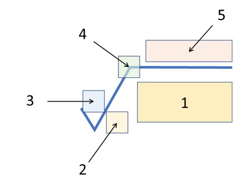
Indications on drawings (Digital Surf)
Surface roughness symbols are always linked to a specific surface on an engineering drawing. Instead of describing the finish in long notes, the drawing places a symbol next to the feature that needs attention. Reading the symbol correctly helps you identify which surface it applies to, the finish that must be achieved, and any additional manufacturing instructions before machining begins.
Reading Surface Roughness Callouts
Start by locating the leader line connected to the symbol.
The leader points to the exact surface that carries the finish requirement.
Next, read the information attached to the symbol.
A simple callout may only include a roughness value such as Ra 1.6 um, while more detailed callouts can include the machining method, lay direction, and material removal requirement.
It is also worth checking the drawing notes. Some drawings apply one surface finish to most features and only add separate callouts for surfaces that require a different finish.
Reading the general note first helps you avoid assuming every symbol represents a unique requirement.
Interpreting Multiple Surface Finish Requirements
Surface Finish with Callout Symbols (CNC Cookbook)
Complex parts often require different surface finishes because each feature performs a different function. Instead of applying the same finish everywhere, engineers specify roughness based on how each surface will be used.
Typical examples include:
- Bearing seats usually require a fine surface finish for accurate fit and smooth operation.
- Sealing surfaces need controlled roughness to reduce leakage and improve sealing performance.
- Mounting surfaces require good flatness and a consistent finish for stable assembly.
- Sliding or contact surfaces often receive a finer finish to reduce friction and wear.
- External or cosmetic surfaces may use a standard finish if they do not affect part function.
- Non-functional faces are commonly left with the finish produced by the machining process to reduce manufacturing time and cost.
| Feature | Typical Surface Finish Consideration |
|---|---|
| Bearing seats | Fine finish to support smooth bearing installation and operation. |
| Sealing faces | Controlled finish to help create an effective seal. |
| Shaft journals | Smooth finish to reduce friction and wear. |
| Threaded holes | Surface finish is usually less critical unless specified on the drawing. |
| Mounting faces | Flat, consistent finish to improve component contact. |
| External cosmetic surfaces | Finish selected mainly for appearance or coating preparation. |
| Internal pockets and cavities | Standard machined finish unless another value is specified. |
Common Surface Roughness Symbol Examples
Surface roughness symbols become much easier to understand when you see how they are applied to actual manufacturing drawings. Although the symbol looks the same, the specified roughness value usually depends on the machining process and the function of the surface.
Milling Drawing Example
CNC milling surface finish (Engineering Choice)
A machined plate may have a callout such as Ra 3.2 um on its top face. This tells the machinist that the milled surface should achieve an average roughness of 3.2 um after machining.
This finish is commonly specified for mounting faces, brackets, machine bases, and structural components. It provides a clean machined surface without adding unnecessary finishing operations. If the drawing includes a material removal indicator, the surface must be machined rather than left in its raw condition.
Turning Drawing Example
A shaft drawing may specify Ra 1.6 um on the bearing seat or journal diameter. This finish is finer than a standard milled surface and is commonly achieved through finish turning.
The smoother surface helps rotating components fit correctly and reduces friction during operation. Other areas of the same shaft may use a higher roughness value because they do not contact bearings or mating parts. Always check each callout instead of assuming one finish applies to the entire component.
Grinding Drawing Example
Critical surfaces often require grinding to achieve a finer finish. A drawing may specify Ra 0.4 um on a sealing face, gauge surface, or precision guide. Grinding is often specified after heat treatment because finish turning alone may no longer achieve the required roughness or dimensional accuracy.
Grinding removes a small amount of material after machining to improve the surface finish. Engineers typically apply this requirement only to functional surfaces because grinding increases production time and manufacturing cost. Surfaces that do not influence assembly or performance usually remain at their machined finish instead of receiving additional grinding.
Reading Surface Finish Requirements for Different Features
Not every feature on a component needs the same level of surface finish. Engineers assign roughness values according to the job each surface performs.
Before production starts, engineers usually review every surface-finish callout along with dimensions, tolerances, and material specifications. Looking at these requirements as a complete set reduces machining changes later and helps inspection teams verify the finished part more efficiently.
Surface Roughness Symbol Standards
Surface roughness symbols follow standardized rules so engineers, manufacturers, and inspectors interpret drawings the same way. Although ISO and ASME use similar principles, their notation and documentation can differ. Knowing which standard a drawing follows helps prevent misinterpretation during production.
ISO 1302
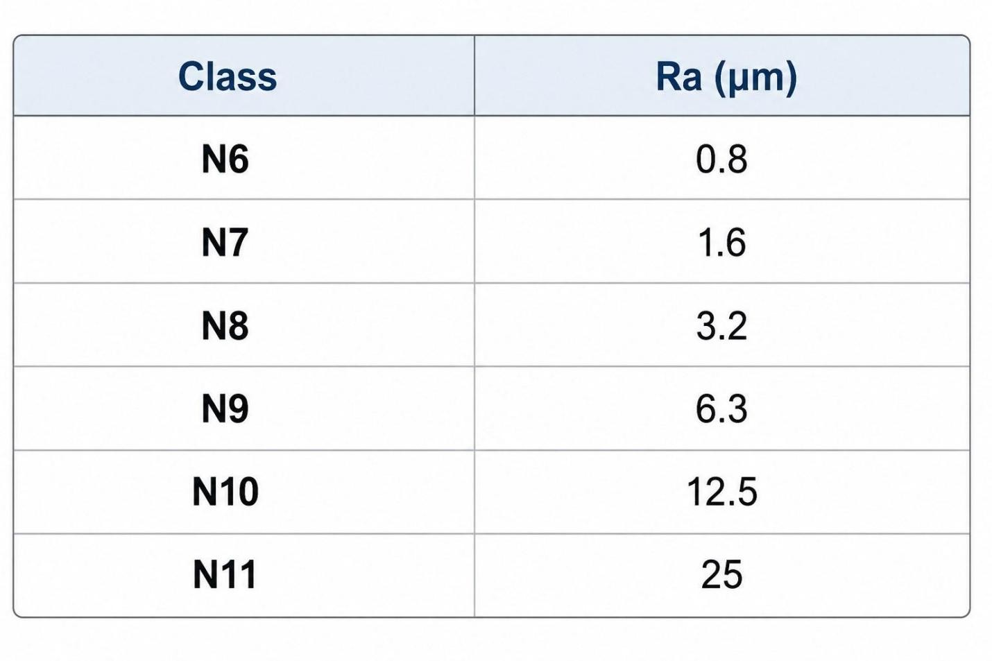
Roughness classes as indicated in the ISO 1302 standard (ResearchGate)
ISO 1302 is the most widely used international standard for surface texture symbols. It defines the symbol format, material removal indicators, roughness parameters, lay direction, machining allowance, and other supplementary information.
Most engineering drawings used in Europe and many international manufacturing projects follow ISO 1302, making it the standard many CNC shops work with today.
ASME Surface Finish Symbols
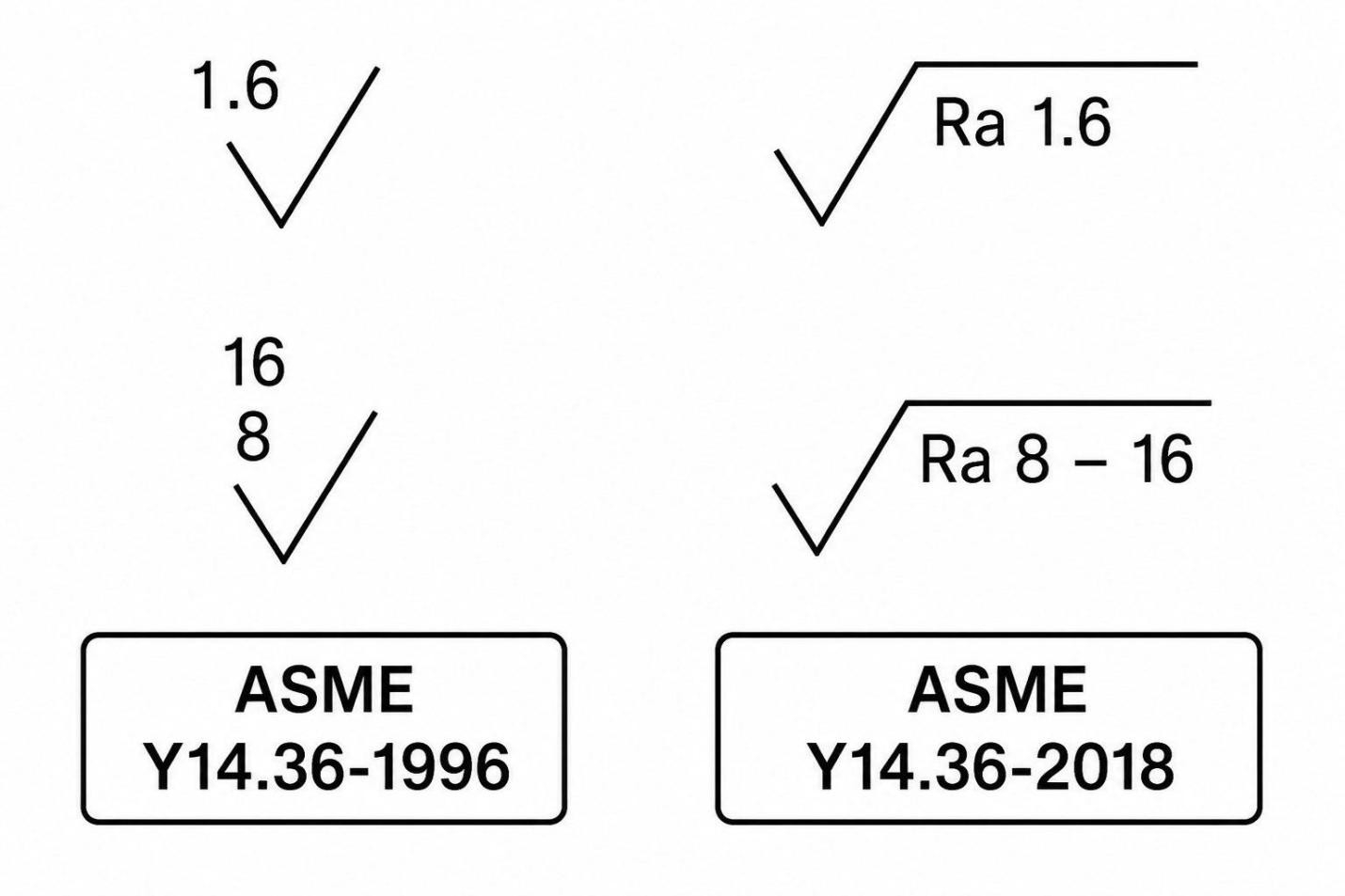
ASME Surface Finish Symbol
The ASME standard is commonly used on engineering drawings in the United States. It also specifies surface finish requirements but follows the ASME drawing practices and terminology. Roughness values such as Ra remain common, although the presentation of symbols and notes may differ from ISO drawings.
Engineers working with North American suppliers often encounter ASME surface finish callouts on mechanical and industrial components.
Key Differences Between ISO and ASME
Both standards communicate the same manufacturing objective, a defined surface finish. The main difference lies in how the information is presented on engineering drawings, so engineers should always identify the drawing standard before interpreting surface finish requirements.
| Feature | ISO 1302 | ASME |
|---|---|---|
| Primary use | International engineering drawings | North American engineering drawings |
| Governing standard | ISO 1302 | ASME Y14.36 (Surface texture measurement requirements are defined in ASME B46.1.) |
| Symbol format | ISO surface texture symbols | ASME surface finish notation |
| Common applications | Global manufacturing and exports | U.S.-based manufacturing projects |
| Roughness parameters | Ra, Rz, Rq, Rt and others | Commonly uses Ra with additional parameters as required |
How to Specify Surface Roughness Symbols Correctly
Specifying a surface finish starts with the function of the feature, not the machining process. Every roughness value should support the way the part fits, seals, slides, or contacts another component. Adding a finer finish than necessary increases machining and inspection work without improving part performance.
Selecting an Appropriate Roughness Value
- Choose the roughness value according to the function of the surface.
- Use finer roughness values for bearing seats, sealing faces, and sliding surfaces.
- Apply standard machined finishes to mounting faces and general contact surfaces.
- Leave non-functional surfaces with a coarser finish unless the drawing specifies otherwise.
- Check mating parts before selecting the finish to maintain surface compatibility.
- Specify only the roughness parameter required for inspection, such as Ra or Rz.
Matching Surface Finish to Manufacturing Processes
- Select a finish that the manufacturing process can achieve consistently.
- Use milling or turning for standard machined finishes.
- Specify grinding for finer finishes that machining alone cannot achieve.
- Use polishing or lapping only for surfaces requiring an extremely smooth finish.
- Consider the workpiece material, since achievable roughness varies between aluminum, steel, titanium, and plastics.
- Confirm that the selected process can produce the required finish without unnecessary secondary operations.
Avoiding Over-Specification
- Apply surface finish requirements only where they provide a functional benefit.
- Avoid assigning the same fine finish to every surface on the drawing.
- Add surface roughness symbols only to features that influence assembly, sealing, wear, or movement.
- Do not specify lower roughness values simply because they appear better on paper.
- Review each callout before releasing the drawing to remove unnecessary finish requirements.
- Keep the drawing clear by using general surface finish notes whenever the same specification applies to multiple surfaces.
Common Mistakes When Using Surface Roughness Symbols
Even a small mistake in a surface finish callout can create confusion during machining and inspection. Some errors increase production costs, while others result in parts that fail to meet their intended function. Reviewing every callout before releasing a drawing helps avoid unnecessary rework.
Confusing Surface Roughness with Surface Texture
Surface roughness and surface texture are closely related, but they are not identical.
Common Mistakes
- Referring to every ISO 1302 callout as a surface roughness symbol, even when it includes additional surface texture information.
- Specifying only a roughness value when the drawing also requires lay direction or another surface characteristic.
- Assuming two surfaces with the same Ra value have identical surface characteristics.
- Ignoring supplementary symbol elements that provide manufacturing or inspection instructions.
Using Incorrect Roughness Parameters
Each roughness parameter describes the surface differently. Using the wrong one can lead to inspection issues or incorrect manufacturing results.
Common Mistakes
- Using Ra when the design specifically requires Rz or another parameter.
- Omitting the roughness parameter and specifying only a numerical value.
- Mixing units or measurement standards within the same drawing.
- Selecting a parameter that does not match the inspection equipment or customer specification.
- Copying roughness values from previous drawings without checking the feature's function.
Missing or Incomplete Surface Finish Callouts
Incomplete callouts often force machinists and inspectors to make assumptions, which can lead to inconsistent results.
Common Mistakes
- Leaving out the roughness value while adding only the surface finish symbol.
- Missing the material removal indicator when the manufacturing method is important.
- Applying a general surface finish note while critical features require different values.
- Placing the leader line so it is unclear which surface the callout applies to.
- Forgetting supplementary information such as machining allowance, lay direction, or process notes when the drawing requires them.
Best Practices for Surface Finish Drawings
Clear surface finish specifications reduce questions during production and simplify inspection. A well-prepared drawing communicates only the information needed to manufacture the part correctly. Following consistent drawing practices also helps different suppliers interpret the requirements the same way.
Use Standardized Surface Finish Symbols
Using recognized standards makes engineering drawings easier to understand across different manufacturing teams.
- Follow the drawing standard specified for the project, such as ISO 1302 or the applicable ASME standard.
- Use the correct surface finish symbol instead of creating custom notes.
- Specify the required roughness parameter, such as Ra or Rz, together with its value.
- Include supplementary information only if it supports manufacturing or inspection.
- Place each symbol so it clearly points to the intended surface.
Keep Surface Finish Callouts Consistent
Consistent callouts make drawings easier to read and reduce interpretation errors.
- Use the same units and roughness parameters throughout the drawing.
- Apply a general surface finish note if the same finish covers most features.
- Add separate callouts only for surfaces that require a different finish.
- Keep the symbol style and annotation format consistent across all views.
- Review duplicate callouts to remove unnecessary specifications.
Coordinate Surface Finish Requirements with Manufacturing Capability
Surface finish requirements should match the production process available for the part.
- Select roughness values that standard machining operations can achieve whenever possible.
- Reserve grinding, polishing, or lapping for surfaces that truly require a finer finish.
- Consider the workpiece material before assigning very fine surface finishes.
- Discuss critical surface requirements with the manufacturing team during the design stage.
- Confirm that the specified finish can be measured using the available inspection equipment before releasing the drawing.
FAQs About Surface Roughness Symbols
Q: What is a surface roughness symbol?
A surface roughness symbol is a standardized symbol on an engineering drawing that specifies the required surface finish for a feature. It communicates the roughness requirement and may also include additional manufacturing or inspection information.
Q: What is the difference between a surface roughness symbol and a surface texture symbol?
A surface roughness symbol specifies the required roughness parameter, such as Ra or Rz. A surface texture symbol has a broader scope and can also define lay direction, machining allowance, manufacturing method, and other surface characteristics.
Q: What does Ra mean on a drawing?
Ra represents the arithmetic average roughness of a surface profile. It is the parameter most commonly used to specify and verify surface finish on engineering drawings.
Q: What standard defines surface roughness symbols?
ISO 1302 defines the symbols and notation used on international engineering drawings. Engineering drawings prepared under ASME standards follow the corresponding ASME surface finish conventions.
Q: How do I read a surface roughness callout?
A surface roughness callout is interpreted by identifying the feature it references, reading the specified roughness parameter and value, then checking for any supplementary information such as material removal requirements, lay direction, or machining notes.
Q: Can multiple surface finish symbols appear on one drawing?
Engineering drawings often contain multiple surface finish symbols because different features perform different functions. Critical surfaces may require finer finishes, while general machined faces use standard surface finish requirements.
Q: How do engineers choose the correct roughness value?
The required roughness value depends on the function of the surface. Features used for sealing, bearing support, sliding contact, or precision assembly generally require finer finishes than non-functional machined surfaces.
Q: Does every machined surface require a surface roughness symbol?
Many engineering drawings use a general surface finish note that applies to all machined surfaces. Individual surface roughness symbols are added only to features that require a different finish from the general specification.
Conclusion About Surface Roughness Symbols
Reading surface roughness symbols correctly is only the first step. The specified finish also needs to match the machining method, inspection approach, and functional requirements of the part. An appropriate specification helps avoid unnecessary machining while ensuring critical surfaces perform as intended.
Precision CNC Machining Service
At JLCCNC, engineering drawings are reviewed before production to confirm that specified surface finishes can be manufactured efficiently. Upload your drawing to receive a CNC machining quote for your custom part.
Popular Articles
• Surface Finish in Machining, Types, Charts & Testing
• Anodizing vs. Hard Anodizing: The Differences in Surface Treatment Techniques
• Anodized Aluminum Colors: Options, Limits, and Real-World Results
• Explanation of different material surface treatment technologies in CNC machining
• How to choose between Laser marking and UV printing?
Keep Learning
Surface Finish in Machining, Types, Charts & Testing
What is Surface Finish in Machining? At its core, surface finish in machining refers to the small-scale irregularities left on the surface of a part after machining. These irregularities are typically grouped into three categories: Roughness: The fine, closely spaced deviations caused by the cutting process itself. Roughness depends heavily on feed rate, tool sharpness, and cutting speed. Waviness: Larger, more widely spaced variations caused by machine tool vibration, deflection, or thermal distortio......
CNC Machining Surface Roughness: A Practical Guide
Why Surface Roughness Matters in CNC Machining When we talk about CNC machining, precision isn't just about hitting the right dimensions, it’s also about how the surface feels and performs. Surface roughness describes the fine irregularities left on a machined surface, and it directly impacts how a part behaves in the real world. So, what is surface roughness? In simple terms, it's the measure of tiny peaks and valleys created by the cutting process. While they might look smooth to the naked eye, thes......
Optimizing Manufacturing Efficiency: A Guide to Computerized Numerical Control (CNC) Machining Surface Finishes
CNC Surface Finishes: Types, Costs, and How to Choose Quick Answer: Choose an as-machined finish when cost and dimensional stability matter most. Use bead blasting or brushing for a uniform cosmetic appearance, anodizing for aluminum corrosion resistance, hard anodizing for wear, and laser marking or UV printing for identification. Confirm material, tolerance, color, masking, and end-use environment before quoting. A CNC-machined part comes off the machine functional but rarely finished — tool marks, ......
Anodizing vs. Hard Anodizing: The Differences in Surface Treatment Techniques
Quick Answer: Choose Type II anodizing when corrosion resistance, color, and cosmetic appearance are the main requirements. Choose Type III hard anodizing when the part needs greater wear resistance and the coating thickness can be accommodated in the fit and tolerance plan. Confirm alloy, coating thickness, color, sealing, and critical dimensions before release. An aluminum bracket for an outdoor enclosure and a hydraulic cylinder rod both might get anodized — but specifying the same process for both......
How to Remove Anodizing from Aluminum Parts
Key Takeaways Chemical stripping is commonly used when anodizing needs to be removed from most or all of an aluminum part, but the process can also attack the underlying aluminum if it is not controlled. Mechanical removal works well for accessible areas but can change the surface texture and remove more base metal than intended. CNC machining gives better control when a defined anodized area needs to be removed from a precision part. Laser-based removal can be useful for controlled localized treatmen......
Anodizing Thickness: How Much Does It Add?
Anodizing Thickness and Dimensional Change at a Glance Feature Approximate dimensional effect One coated external surface +0.5 × coating thickness Outside diameter across two coated surfaces +1 × coating thickness Bore diameter with two coated walls −1 × coating thickness 60° thread pitch diameter Changes by about 4 × surface-growth amount, or about 2 × coating thickness under the 0.5× growth assumption Dimensional estimates below use the 0.5 × coating-thickness surface-growth relationship given in MI......