GD&T Symmetry: Symbol, Tolerance & Measurement Guide
15 min
- What Is GD&T Symmetry?
- GD&T Symmetry Symbol and Drawing Callout
- How Does GD&T Symmetry Tolerance Work?
- How Is GD&T Symmetry Measured?
- GD&T Symmetry vs. Position vs. Profile
- Why Is GD&T Symmetry Still Found on Legacy Drawings?
- GD&T Symmetry FAQs
- Conclusion About GD&T Symmetry
Key Takeaways
- GD&T symmetry controls the position of a feature's derived median points in relation to a specified datum.
- The symmetry tolerance creates a zone around the true center plane. The median points of the controlled feature must stay within this zone.
- The GD&T symmetry symbol appears in the feature control frame with the tolerance value and datum reference.
- Symmetry is different from a size tolerance because it controls the centered relationship of a feature, not simply its width or thickness.
- A CMM can be used to check symmetry by measuring the feature surfaces and calculating their median points.
- The drawing must clearly identify the datum and the feature being controlled before the symmetry requirement can be inspected.
GD&T symmetry is a geometric tolerance that controls the location of derived median points from opposed feature elements relative to a datum reference. It ensures that a feature remains centered within a specified tolerance zone.
A feature can be within its size limits and still be off-center. For example, a slot may have the correct width, but its position between two reference surfaces may not be centered as required. GD&T symmetry is used to control this type of condition.
The symmetry tolerance controls the derived median points of a feature relative to a datum center plane or axis. For a slot, this means looking at the center positions between its two opposite surfaces rather than checking each surface separately.
This makes symmetry useful for parts where the feature needs to stay centered around a reference.
In this guide, we will cover the GD&T symmetry symbol, symmetry tolerance, drawing callouts, differences from related GD&T controls, and practical measurement methods for CNC-machined parts.
What Is GD&T Symmetry?
GD&T symmetry (GD&T Basics)
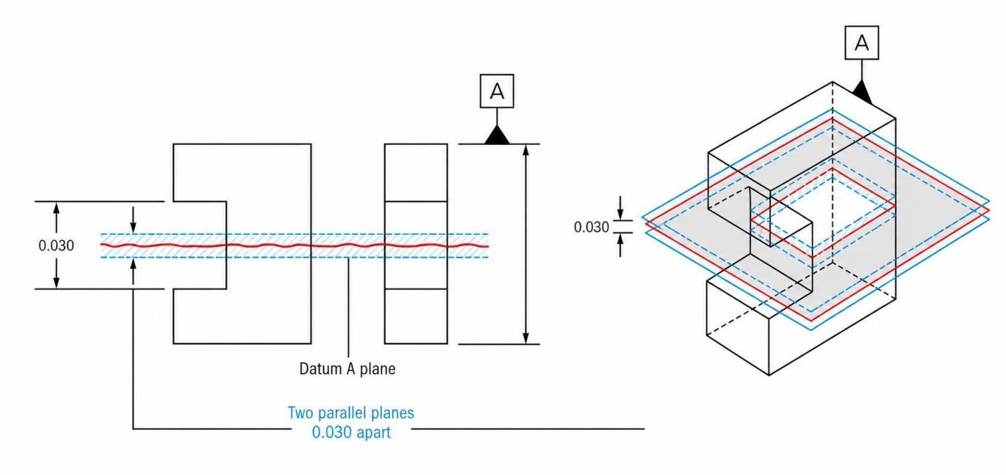
GD&T symmetry controls the relationship of derived median points from opposed or correspondingly located feature elements to the center plane of a datum feature. The tolerance zone consists of two parallel planes equally disposed about that datum center plane. The median points of the controlled feature must remain within these boundaries.
This control is concerned with the feature's centered location, not its size. For example, a slot may have the correct width but still be shifted toward one side of its datum. Symmetry limits that shift by requiring the feature's median points to stay centered within the specified tolerance zone.
Therefore, checking the slot width alone does not establish compliance with a symmetry requirement. The feature can satisfy its dimensional size while its center is displaced from the datum. Symmetry addresses that positional error and keeps the feature centered relative to the referenced datum.
GD&T Symmetry Symbol and Drawing Callout
GD&T Symmetry Symbol (InspectionXpert)
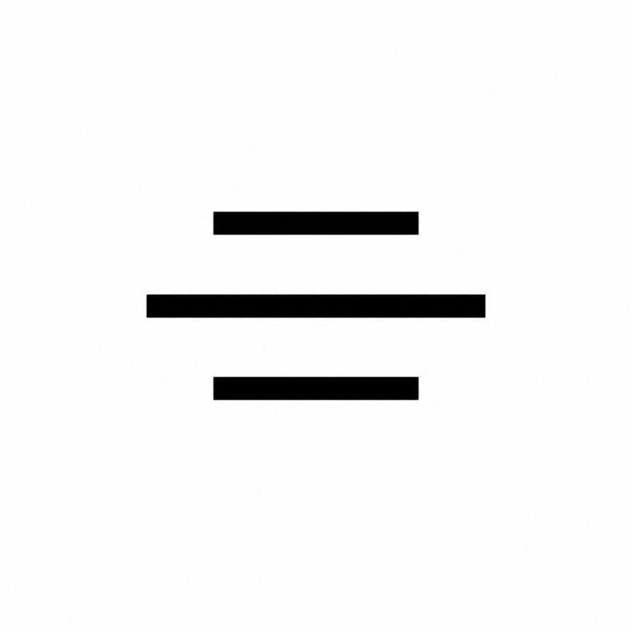
A legacy GD&T symmetry callout is read from the feature control frame attached to the controlled feature. The frame identifies the symmetry symbol and the stated tolerance. Reading these elements in order helps you understand what the drawing requires before inspection or manufacturing begins.
How to Read a Symmetry Callout
Symmetry Positioning (Eng -Tips)
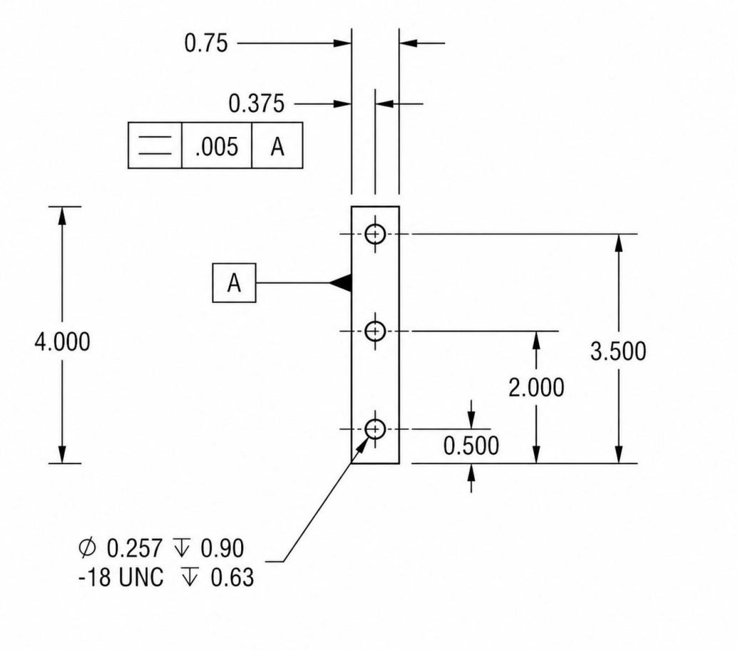
A typical legacy symmetry callout can be represented as:
⌯ | 0.10 | A
Here, ⌯ is the symmetry symbol, 0.10 is the total tolerance value, and A identifies the datum used as the reference center plane.
The 0.10 value defines the width of the symmetry tolerance zone. The controlled feature must remain centered within that zone relative to datum A. The value is a total tolerance, so the boundary planes are located 0.05 mm on either side of the datum center plane when the drawing uses millimetres.
The datum reference is equally important. Datum A establishes the datum reference and, where applicable, the center plane used to evaluate the feature's symmetry. Thus, the same feature can have an acceptable size while failing the symmetry requirement if its location is displaced relative to the datum.
When reading the drawing, first identify the feature attached to the control frame. Then read the tolerance value and datum reference. Also check the drawing's general tolerances, datum scheme, units, and any notes that modify the requirement. These details can affect how the callout is applied during inspection.
Note
Symmetry was removed from ASME Y14.5-2018. For new drawings, Position or Profile may be selected instead, depending on whether the design intent is to control feature location, a derived center, or the actual surface boundary.
Therefore, if you encounter a symmetry callout on an older drawing, it should be interpreted according to the applicable drawing standard and revision rather than automatically replacing it with a modern position tolerance.
How Does GD&T Symmetry Tolerance Work?
GD&T Symmetry Tolerance (Dimensional Consulting)
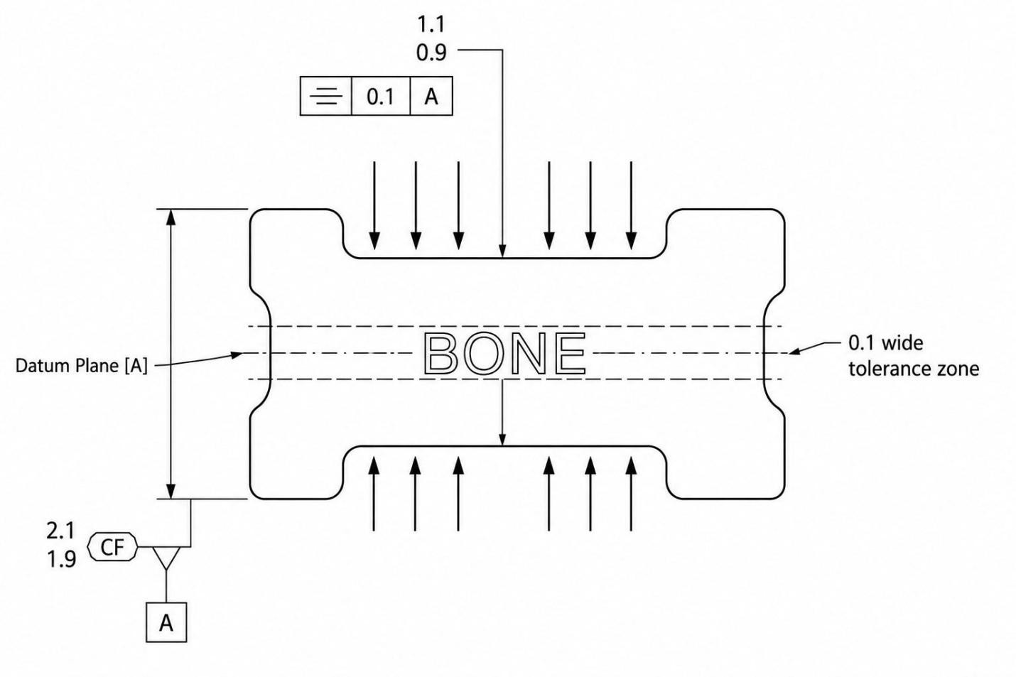
GD&T symmetry evaluates whether a feature remains evenly positioned about a datum center plane. Consider a machined slot with two opposed planar surfaces. The datum establishes the reference from which the slot's center is evaluated. Measurements taken from the two opposite surfaces are then used to establish median points at corresponding sections along the slot.
The symmetry requirement is met when these derived median points remain within the specified tolerance zone around the datum center plane. The control therefore evaluates the feature's centered relationship rather than treating each slot wall as an independently controlled surface.
Symmetry Tolerance Zone
The symmetry tolerance zone consists of two parallel planes positioned equally around the datum center plane. If the drawing specifies a 0.10 mm symmetry tolerance, the total zone width is 0.10 mm.
With the datum center plane established as the theoretical center, the two boundaries are located 0.05 mm on either side of it. Every derived median point must fall within these boundaries.
This creates a centered zone rather than a one-sided limit. A median point displaced 0.04 mm from the datum center plane remains within the zone, whereas a displacement greater than 0.05 mm exceeds the specified tolerance.
Derived Median Points and the Derived Median Plane
For a planar feature such as a slot, corresponding locations on the opposed surfaces can be used to derive median points. These median points define the derived median feature used for evaluating symmetry. For planar opposed surfaces, the resulting median points may establish a derived median plane. CMM measurements may be used to calculate individual median points along the feature, which collectively define the derived median plane.
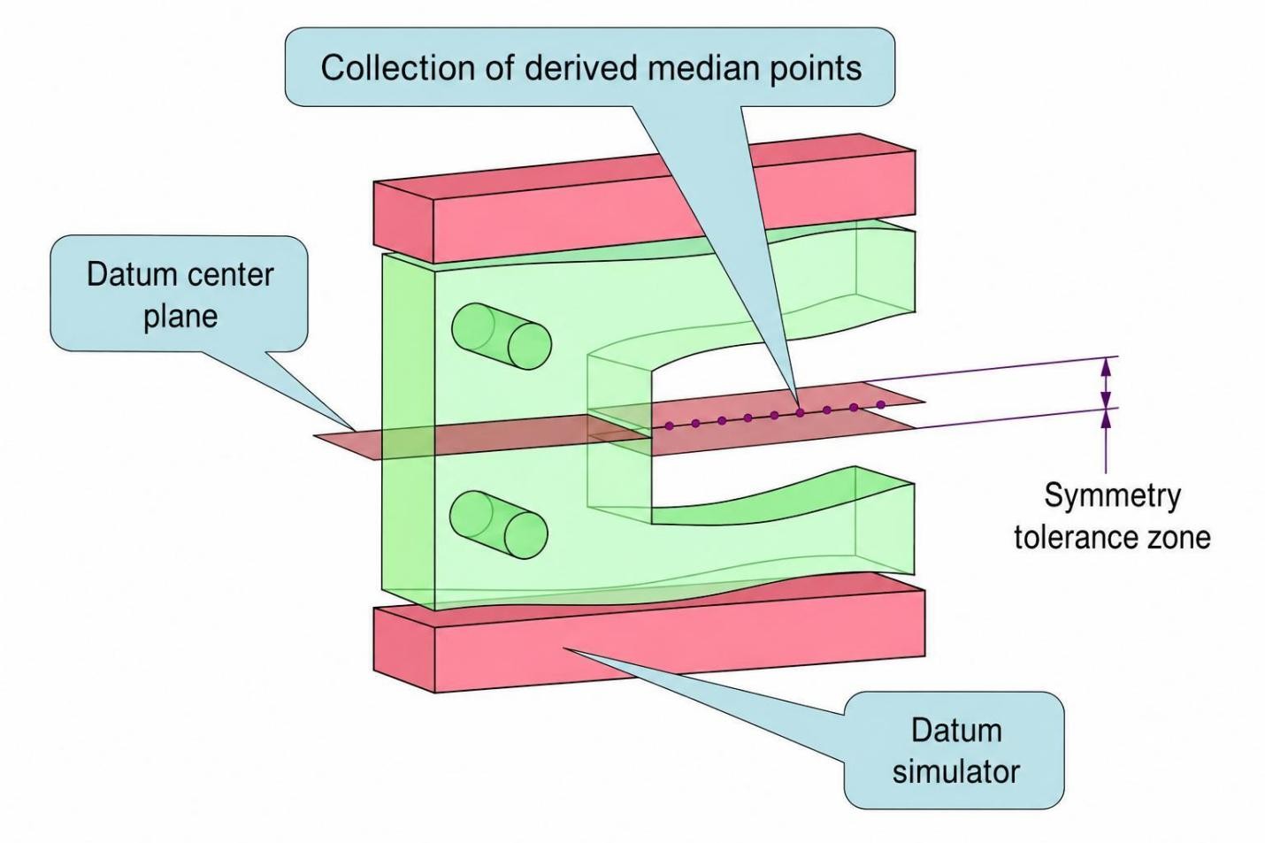
Derived Plane Symmetry Tolerance Zone (Tec - Ease)
For the slot, corresponding points are taken from the two opposite surfaces at the same cross-section. The midpoint between those surface locations forms a derived median point. Repeating this evaluation along the controlled feature produces a set of median points.
These points describe the feature's centered location. If they remain within the symmetry tolerance zone, the feature satisfies the positional requirement. If one or more points extend beyond the zone, the symmetry requirement is not met.
The individual slot surfaces are not the direct target of the symmetry control. Their measured locations are used to establish the median points. Therefore, a surface can have local variation while the derived center relationship remains within the specified zone.
Symmetry Tolerance Example
Suppose a slot has a 20.00 mm basic width and carries a symmetry tolerance of 0.10 mm relative to datum A. Datum A establishes the applicable datum reference for the symmetry evaluation. Depending on the datum feature and drawing definition, this reference may be a datum plane or datum axis rather than a center plane itself.
In one section, the two slot surfaces measure 9.97 mm and 10.03 mm from the datum center reference in opposite directions. Their midpoint lies at 0.03 mm from the theoretical center plane. In another section, the midpoint is 0.06 mm away.
The first section falls inside the ±0.05 mm zone, but the second does not. Therefore, the slot fails the symmetry requirement even though its individual surface dimensions may remain within their specified size limits.
Inspection must evaluate the derived median geometry separately from size and surface-location results.
How Is GD&T Symmetry Measured?
A legacy GD&T symmetry requirement is typically inspected by first establishing the specified datum and then measuring the opposed surfaces of the controlled feature. For a machined slot, a CMM can capture points along both walls and use the measured surface locations to establish corresponding median points.
The inspection is not simply a matter of comparing each wall with a dimension on the drawing. The measured surface data must be related to the datum reference and evaluated as a centered feature against the specified symmetry zone.
Establishing the Datum and Measurement Setup
The CMM first establishes the datum reference defined by the feature control frame. This creates the reference center plane used for the symmetry evaluation. The part must be properly aligned so that the measured feature is evaluated in the correct datum coordinate system.
For a slot, the probe then measures the two opposite walls at selected sections along the controlled length. The measurement strategy should cover the feature sufficiently to identify positional variation rather than relying on a single section.
Surface condition also matters during setup. Burrs, chips, damage, or localized machining marks can influence probe contact and distort the measured surface location. The inspection setup should therefore use clean, stable surfaces and a measurement strategy appropriate to the feature geometry.
The measurement strategy should be defined before inspection because sparse point sampling can miss local variation in the opposed surfaces, especially on long or poorly accessible machined features.
Measuring and Deriving the Median Points
The CMM records the locations of corresponding points on the two opposing slot walls. At each section, the midpoint between the paired surface locations establishes a derived median point.
For example, if the two opposed slot walls are 9.98 mm and 10.06 mm from the datum center plane in opposite directions, the derived median point is offset from the datum center plane by 0.04 mm, calculated as (10.06 − 9.98) / 2.
The important measurement result is the location of these median points relative to the datum center plane. The individual wall measurements provide the input, but they are not themselves the final symmetry result.
Evaluating the Symmetry Requirement
Once the median points have been derived, the CMM software evaluates their locations against the specified symmetry tolerance zone. With a 0.10 mm total symmetry tolerance, the acceptable zone extends 0.05 mm on either side of the datum center plane.
If every evaluated median point remains inside those limits, the feature passes the symmetry requirement. If any required median point falls outside the tolerance zone, the feature fails.
The inspection report should distinguish the symmetry result from other characteristics such as slot width, surface location, or form. A slot can meet its size requirement while still failing symmetry because its median-point locations are displaced from the datum center plane.

Precision CNC Machining Service
For CNC-machined parts with legacy symmetry requirements, JLCCNC can review the CAD model, drawing datums, critical tolerances, and inspection requirements before machining.
GD&T Symmetry vs. Position vs. Profile
Symmetry, Position, and Profile can appear similar when the drawing requirement concerns where a feature should sit relative to a datum. However, they evaluate different geometric relationships.
Symmetry evaluates the centered relationship of opposed surfaces through their derived median points. Position is commonly used to control the location and orientation of features relative to datums. Profile controls the complete surface within a defined boundary. Therefore, selecting between these controls depends on whether the design intent concerns a feature's axis or center, its median relationship, or the actual surface boundary.
Symmetry vs. Position
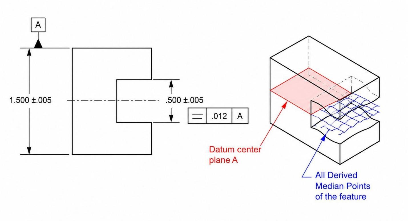
Symmetry Position (dimcax.com)
Position is often selected for new drawings when the design intent is to control feature location relative to datums. For example, a hole pattern can be located from basic dimensions and controlled with a position tolerance relative to the applicable datums.
A legacy symmetry callout, by contrast, evaluates the derived median points of opposed surfaces. The two controls can therefore produce different inspection results even when they appear to address a similar centering requirement.
For modern drawing practices, position is often preferred when the intended requirement is feature location. The exact control still depends on the feature and the applicable ASME Y14.5 requirements.
Symmetry vs. Profile
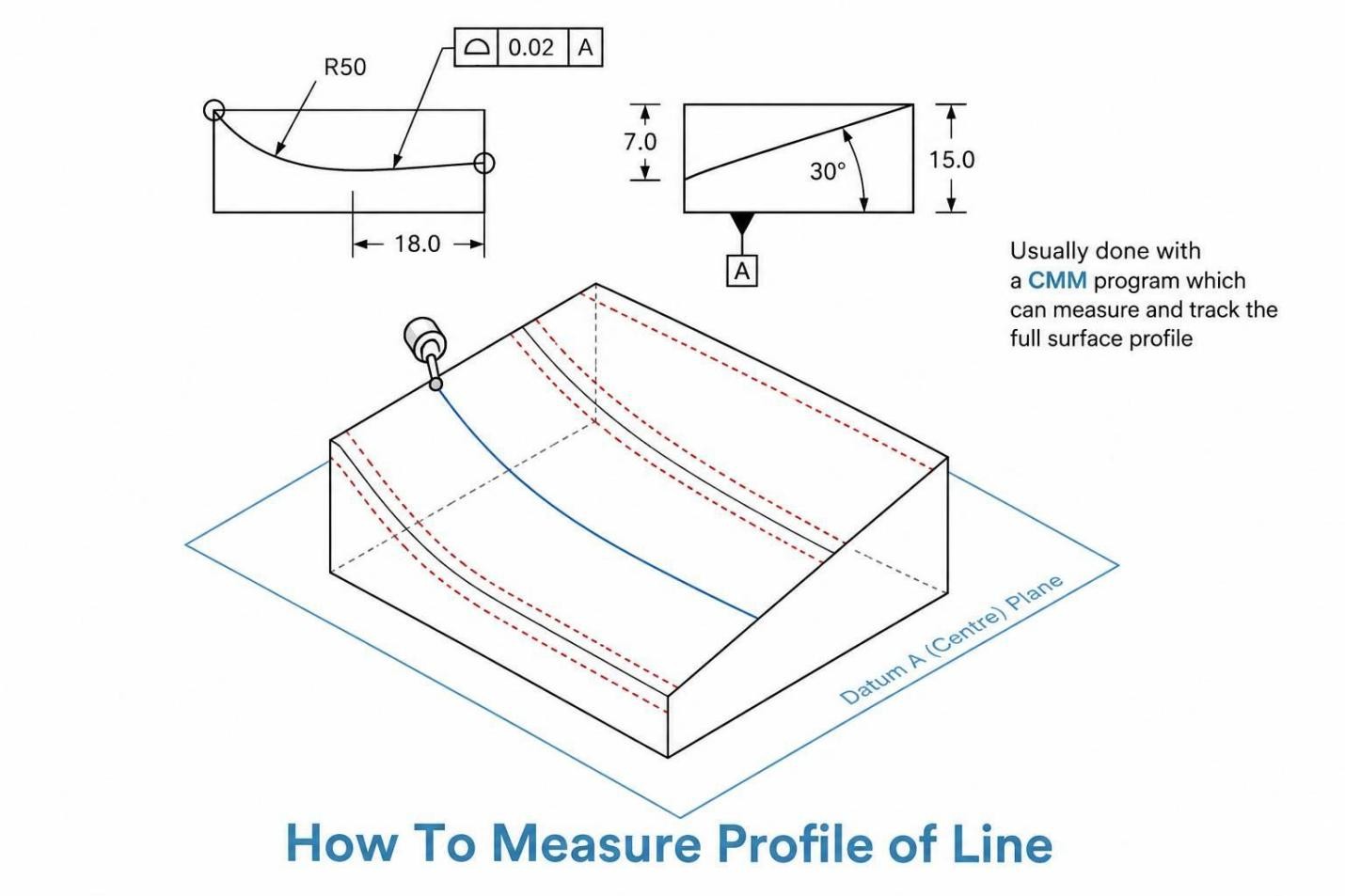
GD&T profile of a line (ECOREPRAP)
Profile of a surface becomes more appropriate when the actual surface boundary, including its location and orientation, must be controlled relative to the datum reference frame. A profile tolerance can limit the complete surface relative to its theoretically exact geometry and specified datums.
For example, if a machined surface must follow a defined contour while maintaining its required location and orientation, the profile addresses that surface directly. Symmetry does not provide the same surface control because its evaluation is based on derived median points.
Note
The main distinction is the characteristic being evaluated. Symmetry evaluates the centered relationship of opposed surfaces, Position controls the location of a feature or derived center relative to datums, and Profile controls the actual surface boundary.
Therefore, replacing a legacy symmetry callout with another control should not be based only on the symbol. The drawing's design intent must first be identified, then the control selected to address that specific requirement.
| What it evaluates | Typical design intent | Key distinction | |
|---|---|---|---|
| Symmetry | Derived median points of opposed or corresponding elements | Control a centered relationship about a datum | Legacy control in ASME Y14.5 |
| Position | Location of a feature of size or derived axis/center plane | Locate a feature relative to datums | Commonly used for feature location |
| Profile | Actual surface or line elements relative to true profile | Control surface location, orientation, and form | Controls the surface itself |
Why Is GD&T Symmetry Still Found on Legacy Drawings?
Symmetry callouts still appear on engineering drawings released under earlier revisions of ASME Y14.5. A legacy callout remains part of the drawing requirement unless the document is formally revised, so it should be inspected against the standard that governs that drawing.
ASME Y14.5-2018 removed symmetry from the current geometric characteristic set; its former definition and symbol are retained in Nonmandatory Appendix D to help interpret existing drawings. This change does not invalidate an older drawing. For example, a released drawing may still specify 0.10 mm symmetry for a machined slot, and that requirement remains applicable unless the drawing is revised.
Do not replace the callout with Position simply because Position is used on newer drawings. Symmetry evaluates derived median points, whereas Position and Profile address different design requirements. A CMM inspection must follow the actual drawing requirement, including the applicable datum scheme and drawing revision.
What to Use for New GD&T Requirements
For new designs, select the control from the functional requirement. Use Position when the feature location or derived center must be controlled from datums; use Profile when the actual surface boundary needs control. For an existing part, confirm the governing standard before changing the interpretation or inspection method.
Precision CNC Machining Service
Professional manufacturing, fast turnaround, and quality assurance.
GD&T Symmetry FAQs
Q: Is GD&T Symmetry Still Used?
You can still encounter symmetry on existing engineering drawings, particularly those released under earlier versions of ASME Y14.5. It was removed from ASME Y14.5-2018, so it is not a control used for new requirements under that revision. When a legacy drawing contains the symbol, check the drawing revision and governing GD&T standard before interpreting or changing the requirement.
Q: Can Symmetry Tolerance Use MMC or LMC?
No, the legacy symmetry control does not use material condition modifiers such as MMC or LMC. Its tolerance is applied to the derived median points of the controlled feature relative to the specified datum reference.
The ASME symmetry tolerance was applied regardless of feature size; MMC and LMC modifiers were not permitted on the symmetry tolerance. If a legacy drawing appears to combine symmetry with a material condition modifier, verify the drawing standard and revision before interpreting the callout.
Q: What Is the Difference Between Symmetry and Position?
Symmetry evaluates the derived median points of opposed surfaces relative to a datum center plane. Position is used to control the location of a feature or feature pattern relative to specified datums.
For example, symmetry can be found on a legacy drawing for a slot where the requirement concerns the slot's centered relationship. True position is commonly used on newer drawings when the design intent is to locate a feature from basic dimensions and datums.
The two controls should not be treated as interchangeable without reviewing the feature and the intended functional requirement.
Conclusion About GD&T Symmetry
Under ASME Y14.5-2018, symmetry is a former geometric control that evaluates the derived median points of opposed or correspondingly located feature elements relative to a datum center plane or axis. The symmetry control remains relevant when interpreting legacy ASME drawings, while ISO 1101 continues to define symmetry as a geometric specification.
When you encounter a symmetry callout, start with the drawing revision and governing GD&T standard. Then identify the datum reference, tolerance value, controlled feature, and required inspection method. This prevents a legacy requirement from being interpreted using a different control by mistake.
For new drawings, Position or Profile may provide a clearer way to communicate the intended requirement, depending on whether the requirement concerns feature location or the actual surface boundary.
If you need precision CNC machining for components with defined GD&T requirements, JLCCNC can support prototype and production requirements with engineering-focused manufacturing and inspection capabilities. Review your drawing requirements before requesting a quote so the critical dimensions, datums, and tolerances are clearly identified.
Keep Learning
GD&T Datum: Definition, Types, Symbols, and Datum Reference Frame
Key Takeaways A datum in GD&T is a theoretically exact reference used to locate or orient other features on a part. It is not the physical surface itself. A datum feature is the physical feature identified on the part and used to establish a datum. The datum itself is the theoretically exact geometric reference derived from that feature. Datums become especially important when several features have to work together. A hole pattern, bearing bore, mounting face, or mating surface may need to establish t......
GD&T Runout: Definition, Symbol, Measurement & Tolerance
Key Takeaways Runout limits surface variation while a part rotates around its specified datum axis. The datum feature establishes the axis used for the runout requirement. You compare the full indicator variation during rotation with the tolerance stated on the drawing. Circular runout applies at individual circular sections of the controlled surface. Total runout evaluates the controlled surface across its specified extent. Runout is not a size tolerance, and its value is not determined by the diamet......
GD&T Perpendicularity: Definition, Tolerance & Examples
Key Takeaways Perpendicularity is an orientation control used for a feature specified at 90° to a datum. A surface callout controls the complete surface within two parallel planes set perpendicular to the referenced datum. An axis callout controls the derived axis inside the specified tolerance zone instead of controlling the physical surface directly. Perpendicularity does not establish the location of a feature. A drawing can require another geometric control when position also needs definition. Dat......
Concentricity in GD&T: Definition, Symbol, Tolerance, and Measurement
Key Takeaways Concentricity in legacy ASME GD&T controls the derived median points of a feature relative to a datum axis. It does not simply compare the axes of two fitted cylinders. Check the drawing standard first. Legacy ASME concentricity and ISO concentricity or coaxiality should not be interpreted as equivalent requirements. For the cylindrical example in this guide, the tolerance zone is a cylinder centered on the datum axis. The derived median points of the controlled feature must lie within t......
Engineering Fits: Clearance, Transition, and Interference Fits
Key Takeaways Engineering fits describe the dimensional relationship between two mating parts, specifically whether assembly produces clearance (gap), interference (overlap), or a result that could be either. Clearance fit always produces a gap; the shaft is always smaller than the hole. Interference fit always produces overlap; the shaft is always larger than the hole and force or temperature is needed to assemble. Transition fit can produce either a small clearance or small interference depending on......
What Is Design for X (DFX)? Principles, Types & Applications
Key Takeaways A part can work exactly as intended and still create problems in manufacturing, assembly, inspection, service, or cost. DFX brings these downstream considerations into the design stage, while design changes are still relatively easy to make. DFX principles don't replace functional requirements. They identify where those requirements create downstream problems and find ways to resolve the conflict before tooling, production, or launch. DFX is not a single method. It's a collection of over......