Blade Machining: CNC Milling & 5-Axis Guide
18 min
- What Is Blade Machining?
- Turbine Blade Geometry and Machining Challenges
- How Is Blade Milling Performed?
- 5-Axis CNC for Blade Machining
- Tools and Toolpaths for Blade Milling
- Materials for Blade Machining
- Blade Machining Accuracy and Surface Finish
- Blade Machining FAQs
- Conclusion About Blade Machining
Key Takeaways
- Blade machining follows a changing airfoil shape, so the profile, twist, thickness, and edge geometry have to stay within the drawing requirements.
- 5-axis CNC milling gives better access to twisted and curved blade surfaces and can reduce the need to reposition the part.
- Cutter position and tool orientation have a direct effect on surface finish, cutting load, and access around the airfoil.
- Thin blade sections need proper support during machining because cutting forces can change the finished profile.
- Roughing should leave a controlled amount of stock for semi-finishing and finishing. This gives the final passes enough material to establish the required airfoil.
- Blade inspection should verify the actual airfoil profile, not just length, width, or other basic dimensions.
- Aluminum, stainless steel, titanium, and nickel-based alloys require different machining approaches because their cutting and thermal behavior vary.
- A blade machining RFQ should include the 3D model, engineering drawing, material grade, quantity, tolerances, edge requirements, surface finish, and inspection requirements.
Blade machining is mainly about keeping the finished airfoil close to the required geometry. Unlike a simple prismatic part, the blade can change in curvature, thickness, and twist from one section to another. The leading and trailing edges also need controlled machining because small profile changes can affect the finished part.
The machining plan should start with the blade model and drawing. Material, starting stock, edge condition, surface finish, critical dimensions, and inspection requirements should be reviewed before choosing the tools and toolpaths.
A 3-axis machine can produce some accessible blade surfaces, but increasing twist and curvature can limit tool access and force additional setups. Multi-axis machining allows the tool axis to change relative to the airfoil, while simultaneous 5-axis machining can maintain more suitable cutter orientation as the surface changes.
The finished part should be checked against the CAD model and drawing, particularly at critical airfoil sections and around the leading and trailing edges. For production work, defining these requirements before machining gives the programmer, machinist, and inspector the same target from the start.
What Is Blade Machining?
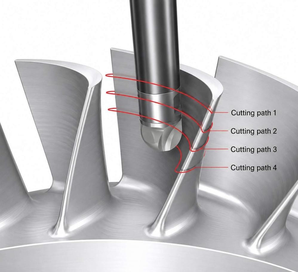
The four cutting paths used in milling a turbine blade (ResearchGate)
Blade machining is the CNC manufacturing of a blade from a cast, forged, or solid workpiece by removing material to produce the required airfoil, root, platform, and edge geometry. The finished part can have a continuously curved profile, changing thickness, and controlled leading and trailing edges.
The main point is that the blade is defined by its three-dimensional profile, not simply by its overall length and width. CNC machining is used to reproduce that profile from the engineering drawing or CAD model while keeping the required dimensions and surface form.
For complex blade geometries, the machining process may use multiple axes so the cutting tool can reach and follow different areas of the profile. The required number of axes depends on the blade geometry and the features that need to be produced.
Turbine Blade Geometry and Machining Challenges
Blade geometry has a direct effect on how the part is machined. The airfoil changes in curvature along its length, while the root, platform, and edge sections have their own dimensional requirements. These changes can limit tool access and leave some areas more difficult to machine without collision or surface errors.
The local thickness also changes from one section to another. Thin areas can deflect under cutting forces, while transition areas between the airfoil and root need controlled material removal to maintain the intended profile.
Blade Profile and Airfoil Surfaces
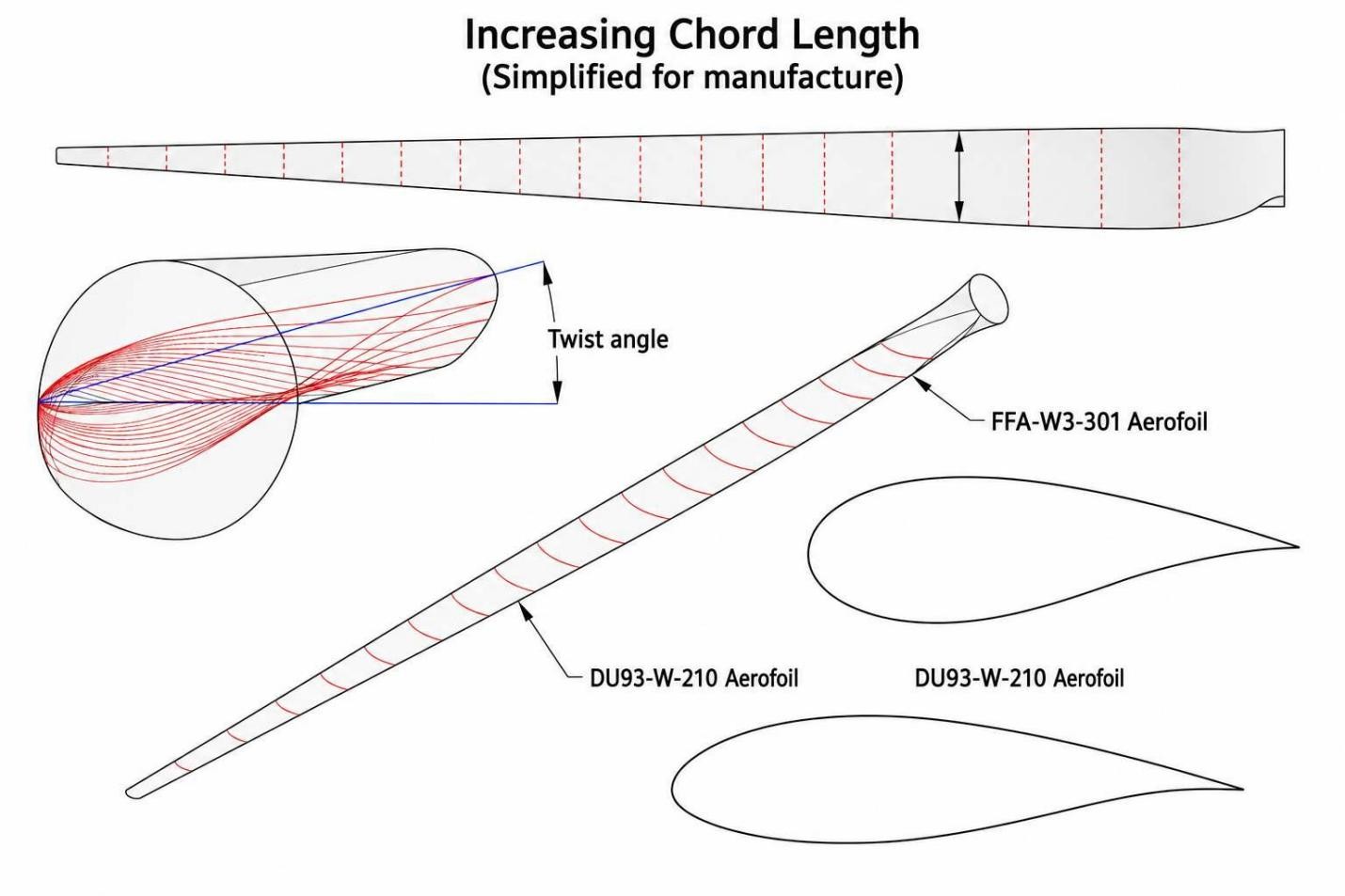
Turbine blade wings design (MDPI)
The airfoil surface is not a constant curve. Its shape changes along the blade, so the cutter has to follow the designed surface rather than simply move along a fixed radius.
Tool access becomes more difficult in deeper or tightly curved areas. The tool angle and cutter size therefore need to suit the local surface geometry. A large cutter may not reach a narrow section correctly, while a smaller cutter can leave more tool marks if the toolpath is not planned properly.
Blade Root and Platform Geometry
The root provides the mechanical interface to the rotor or mounting structure and often contains tightly controlled profiles, radii, and mating surfaces. Depending on the part design and machining sequence, the root may provide datum or workholding features that establish the relationship between the airfoil and the mounting geometry.
The platform forms part of the flow-path boundary and provides the transition between the root and airfoil. Tool access can become restricted around this area, particularly where the airfoil blends into the platform. The machining sequence needs to leave enough access for the required surfaces while protecting the finished features.
Leading and Trailing Edges
The leading edge normally has a controlled radius, while the trailing edge is much thinner and more sensitive to tool engagement. Both regions require dedicated toolpath and stock control rather than being treated as conventional outside edges.
The trailing edge is especially sensitive to excessive cutting force because there is less material supporting the surface. Toolpath direction, cutter engagement, and remaining stock need to be controlled so the trailing edge does not deflect, roll over, or fall below the specified edge thickness.
Thin Sections and Transition Areas
Thin blade sections can move during machining if the cutting force exceeds the support provided by the remaining material and workholding setup. This can lead to profile errors even when the CNC machine itself is operating correctly.
Transition areas can present a different problem. A small change in curvature or thickness can make tool access difficult and increase the chance of leaving excess material. These areas should be evaluated during process planning, with the machining sequence arranged so that stiffness is maintained until the surrounding material has been removed safely.
Blisks present the same airfoil-machining challenges at a higher level because multiple closely spaced blades are integrated with the disk. The narrow passages restrict tool access and make tool orientation, holder clearance, and blade-to-blade consistency critical.
How Is Blade Milling Performed?
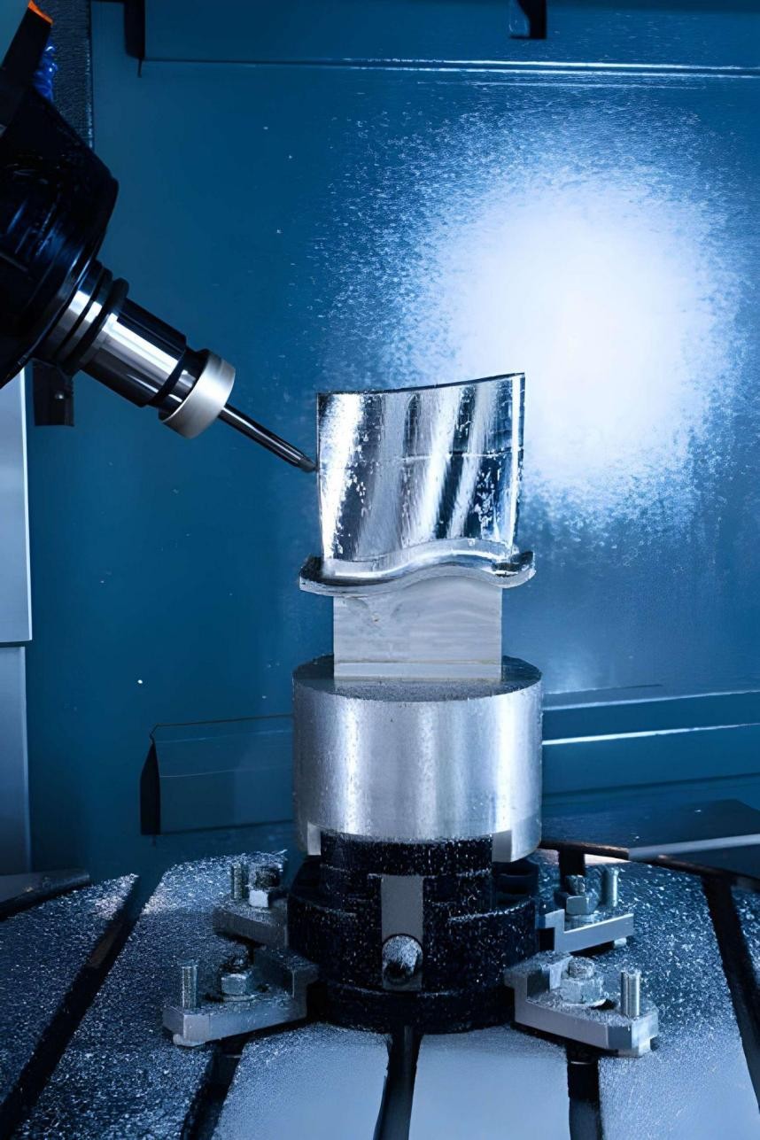
CNC milling machine center produces the turbine blade (iStock)
Blade milling starts with defining the blade surfaces and machining boundaries in CAM. The programmer then plans the material removal in stages so that enough stock remains for the next operation without leaving unnecessary material in difficult areas.
The machining sequence normally moves from roughing to semi-finishing and then final finishing. Each stage has a different purpose. Roughing removes the bulk of the blank, semi-finishing brings the airfoil close to its final form, and finishing controls the final profile and edge geometry.
CAD/CAM Setup and Blade Surface Definition
The CAD model is used to identify the airfoil surfaces, root, platform, leading edge, trailing edge, and the boundaries between them. These surfaces are then defined in the CAM system so the toolpath follows the intended blade geometry.
The programmer also needs to define where the tool can enter and leave the surface. On a twisted airfoil, this is not simply a matter of selecting the entire surface and generating a toolpath. The tool orientation needs to provide access to the required area while keeping the cutter clear of the blade, holder, and surrounding geometry.
Stock allowance is also defined at this stage. Enough material should remain for semi-finishing and finishing, but excessive stock can increase cutting load and make the later operations less predictable.
Roughing the Blade Blank
Roughing removes the majority of the material from the blade blank while leaving a controlled amount on the airfoil and other finished surfaces.
The roughing strategy should avoid sudden increases in cutter engagement as the blade section changes, since unstable cutting loads can increase tool wear and deflect thin regions. Material removal should be planned around the changing blade geometry so the remaining stock stays reasonably uniform before semi-finishing, particularly across regions where the airfoil curvature changes rapidly.
Workholding and datum selection should be established before the airfoil is rough-machined. The setup needs to reference stable features while maintaining access to the surfaces that will be finished later. As material is removed, the remaining structure may become less rigid, so the machining sequence should preserve sufficient support until the critical airfoil surfaces are established.
Semi-Finishing the Airfoil
Semi-finishing brings the airfoil closer to its final profile and removes the uneven stock left by roughing.
The remaining stock is controlled across the curved surface rather than leaving large variations from one area to another. This gives the finishing cutter a more consistent amount of material to remove.
This stage is also useful for checking difficult areas such as tight curvature and transitions near the root and platform. If excessive material remains in one section, the CAM toolpath can be adjusted before the final finishing operation.
Finishing the Airfoil and Blade Edges
Finishing produces the final airfoil surface and brings the leading and trailing edges to their specified geometry. Smaller stepovers and controlled tool movement are commonly used where the drawing requires a smoother surface.
Tool orientation becomes particularly important around the edges. The cutter needs enough access to follow the profile without contacting adjacent surfaces or removing more material than specified.
The final toolpath should also maintain the intended transition between the airfoil and edge sections. This is where profile accuracy is established, so the finished blade should be checked against the CAD model and drawing requirements after machining.

Precision CNC Machining Service
Have a blade CAD model ready for review? Upload the file to JLCCNC to evaluate the machining approach and receive a machining quote based on the part requirements.
5-Axis CNC for Blade Machining
5-axis machining is useful for blade parts because the cutter can approach the airfoil from different directions as the profile changes. This is especially useful for twisted surfaces that are difficult to reach with a fixed tool direction.
Tool Access to Twisted Airfoil Surfaces
The airfoil changes angle along the blade, so some areas cannot be reached effectively with a fixed-axis toolpath. 5-axis movement allows the tool axis to change as the airfoil orientation varies, improving access to the surface and potentially reducing the number of setups required.
Tool Orientation and Cutting Stability
The cutter can be tilted to suit the local airfoil surface. This helps keep cutter engagement more controlled as the profile changes and can reduce sudden changes in cutting load. The selected lead or tilt angle also affects cutter engagement, contact location, holder clearance, and the risk of gouging or excessive cutting load.
Fewer Setups for Complex Blade Geometry
Multi-axis machining can reduce the need to reorient the part between operations, which helps preserve the relationship between the airfoil, root, platform, and other critical features when the setup remains stable.
| Machining approach | Suitable for | Main limitation |
|---|---|---|
| 3-axis | Accessible blade surfaces | Fixed tool direction limits access |
| 3+2-axis | Multi-sided features and simpler blade geometry | Tool orientation changes between operations rather than continuously |
| Simultaneous 5-axis | Twisted airfoils and restricted blade passages | Higher programming and collision-control requirements |
Tools and Toolpaths for Blade Milling
Blade milling needs a cutter and toolpath that follow the airfoil without forcing excessive tool engagement. The blade shape changes continuously from the leading edge to the trailing edge, so tool reach, holder clearance, tool orientation, and contact position must be checked throughout the path.
Cutting Tools and Tool Reach
Ball-nose cutters are widely used for finishing freeform blade surfaces, but the preferred cutter depends on the airfoil geometry, required access, and finishing strategy. Barrel, toroidal, or other form tools can be more efficient on suitable regions because they provide a larger effective cutting radius. The cutter should have enough reach to access the full surface without placing the holder close to the blade.
A long tool can reach deeper sections, but it also increases deflection. A shorter, more rigid setup is preferable where the blade geometry allows it. Cutter diameter also affects how closely the tool can follow small-radius regions around the leading and trailing edges.
Toolpath Strategies for Airfoil Surfaces
The toolpath should follow the blade geometry rather than simply covering the surface with parallel passes.
Point milling uses localized cutter contact to follow a freeform surface, with tool orientation adjusted as required by the blade geometry. It provides flexibility for complex airfoils but may require tighter control of stepover, tool tilt, and cutter engagement to maintain surface quality.
Flank milling uses the cutter flank to machine a ruled or near-developable surface in fewer passes. It is effective when the blade surface can be closely matched to the cutter flank without excessive deviation or gouging.
Flow-line and spiral paths follow the natural direction of the airfoil. These paths can give a more consistent tool motion across the blade and reduce abrupt changes in cutting direction.
For finishing, the path should maintain a controlled contact pattern across the airfoil. Leading and trailing edges usually require closer control because their curvature changes quickly.
Tool Orientation and Collision Avoidance
Tool orientation has to be checked against the blade, hub, shroud, holder, and spindle assembly. A cutter may clear the airfoil while the holder still approaches the adjacent geometry.
Multi-axis machining allows the cutter axis to tilt as the tool moves across the blade. This helps maintain useful cutter contact and keeps the holder away from the component.
Collision checking should cover the complete tool assembly, not just the cutter. It is also useful to check rapid moves and linking motions between passes, since interference can occur outside the cutting path itself.
Holder clearance should be verified throughout the toolpath because a collision-free cutter tip does not guarantee clearance for the holder or spindle.
Materials for Blade Machining
Material choice changes the cutting force, heat flow, tool wear, and deformation behavior during milling. The same cutter and toolpath can behave quite differently in aluminum than in titanium, stainless steel, or a nickel-based alloy.
Common Materials for Machined Blades
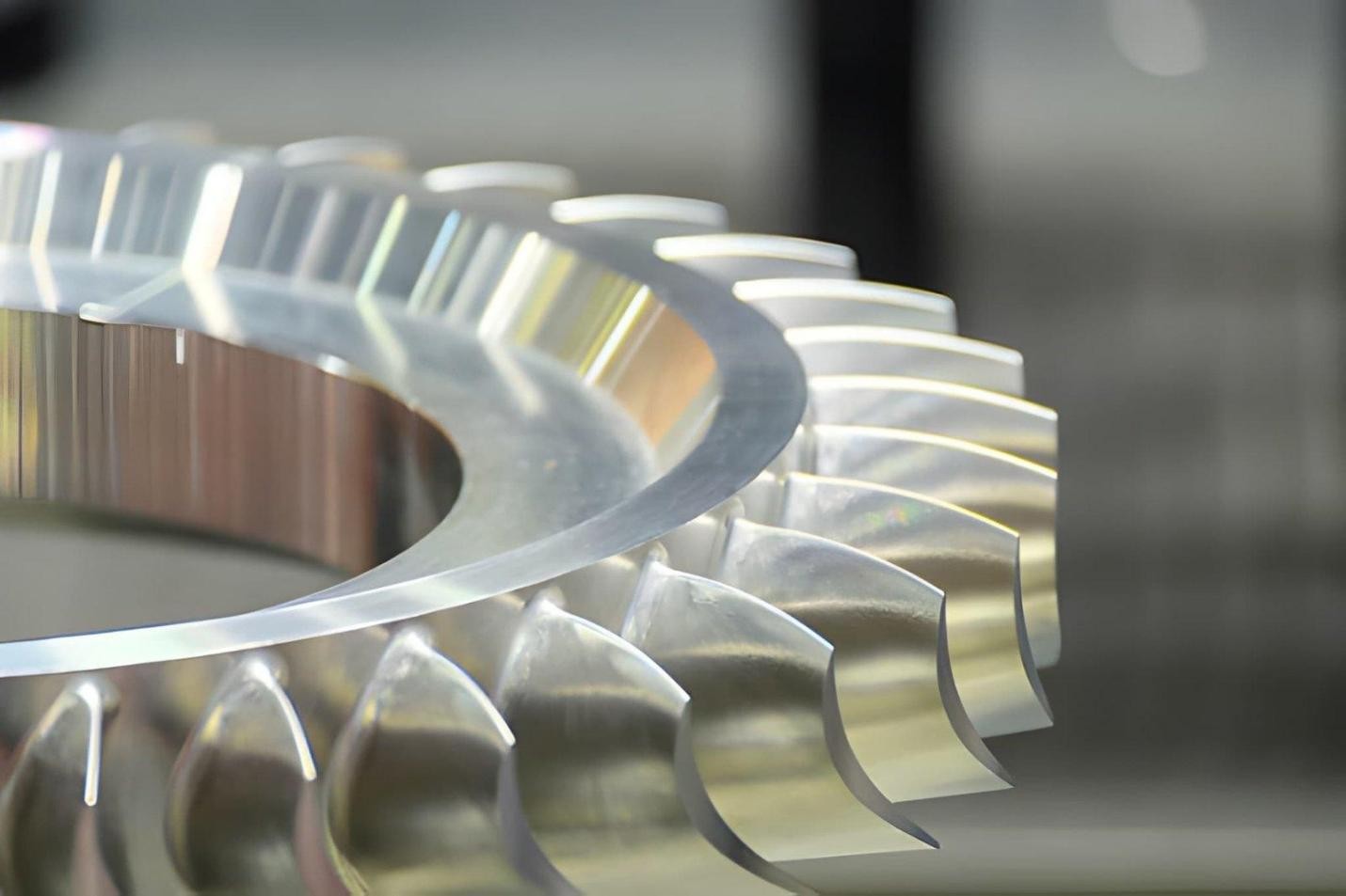
Close-up of an aluminum machined jet engine part (iStock)
Aluminum is relatively easy to cut and allows higher material removal rates. The main concern is chip control and material buildup on the cutting edge, particularly with unsuitable cutting conditions.
Stainless steels generally require higher cutting forces than aluminum and can generate more heat at the cutting zone, depending on the alloy and cutting conditions. Tool wear becomes more significant, especially during long finishing passes on thin blade sections.
Titanium alloys combine high strength with low thermal conductivity, so a larger share of the generated heat remains near the cutting zone. This can accelerate tool wear when cutter engagement or cutting conditions are not well controlled.
Nickel-based alloys are difficult to machine because they retain high strength at elevated temperatures and can generate high cutting forces. Some grades also work-harden readily, so unstable cutting or repeated passes over the same area can accelerate tool wear.
How Material Properties Affect Blade Milling
Material strength affects the force required to remove material. Alloy strength, work hardening behavior, thermal conductivity, and cutting temperature all affect cutting force and tool wear. These effects become more difficult to manage when the blade section is thin and has limited structural stiffness.
Thermal conductivity also changes the cutting condition. Aluminum carries heat away relatively well, while titanium and nickel-based alloys retain more heat near the cutting zone. This increases thermal loading on the cutting edge.
Material ductility affects chip formation and surface behavior. The cutter geometry and engagement should therefore be matched to the selected alloy rather than using one blade-milling setup for every material.
For thin airfoils, the material and section thickness should be considered together. A strong alloy may resist deformation well, yet the same thin section can still move under milling forces if the tool engagement is excessive.
Blade Machining Accuracy and Surface Finish
Blade accuracy depends on how closely the cutter follows the programmed airfoil and how the blade behaves under cutting forces. Tool condition, tool orientation, machine stability, material, and the changing blade geometry can all affect the finished profile.
Blade Profile and Dimensional Accuracy
The airfoil profile must remain within the required dimensional limits across the blade surface. Thin sections are more sensitive to cutting forces, while the leading and trailing edges require careful control because their geometry changes quickly.
Tool deflection, cutter wear, poor tool orientation, and excessive engagement can shift the cutter away from the programmed path. For this reason, the finishing strategy should maintain consistent tool contact and avoid unnecessary changes in cutting direction.
Surface Finish and Surface Integrity
Surface marks on an airfoil can come from the finishing path, cutter condition, tool orientation, or unstable cutting. Large changes in tool engagement can also leave visible transitions between passes.
The surface should be checked for roughness, tool marks, burrs, and local damage, particularly around thin sections and blade edges. Depending on the application, inspection may also need to consider burrs, local tearing, chatter marks, and other surface-integrity defects.
Inspection of Machined Blade Profiles
Complex blade profiles are commonly verified by comparing measured points with the CAD model or specified airfoil profile. A CMM or suitable optical scanning system can capture the airfoil as a point cloud or measured surface, allowing the profile to be evaluated against the nominal CAD geometry rather than relying only on isolated dimensional checks.
Inspection should focus on the characteristics defined by the drawing and blade specification, which may include airfoil sections, profile deviation, thickness, leading- and trailing-edge geometry, and datum relationships. Comparing the measured profile with the nominal geometry shows where material has been left on or removed beyond the required profile.
Inspection should be tied to the drawing datums and specified profile requirements rather than treating the CAD comparison as a standalone visual check.
For blade parts with defined profile or inspection requirements, JLCCNC can review the drawing and CAD model before machining to determine the appropriate process and inspection approach.
Precision CNC Machining Service
Professional manufacturing, fast turnaround, and quality assurance.
Blade Machining FAQs
Q: Can Blade Parts Be Machined With 3-Axis CNC?
3-axis CNC can machine some blade geometries, particularly where the surfaces are accessible from a fixed tool direction. More complex airfoils may need 4- or 5-axis movement to keep the cutter in a suitable position and reach the complete profile.
Q: When Does a Turbine Blade Need 5-Axis Machining?
A turbine blade does not automatically require simultaneous 5-axis machining. 3-axis or 3+2-axis machining may be sufficient when the airfoil surfaces are accessible from fixed tool orientations. Simultaneous 5-axis machining becomes more useful when blade twist, curvature, restricted passages, or holder clearance prevent stable access with indexed setups.
Q: What Materials Are Commonly Used for CNC-Machined Blades?
Common choices include aluminum, stainless steel, titanium, and nickel-based alloys. The material affects cutting force, heat generation, tool wear, and blade deformation, so the machining approach changes with the alloy.
Q: How Are Machined Blade Profiles Inspected?
The finished blade can be measured against its CAD model or specified airfoil profile. CMMs and optical scanning systems can check the airfoil shape, thickness, leading and trailing edges, and other critical geometry.
Q: What Information Is Needed for a Blade Machining Quote?
A useful RFQ should include the 3D CAD model, 2D drawing, material grade, quantity, required tolerances, surface-finish requirements, and inspection requirements. If the blade has defined airfoil sections or datum references, those should also be included.
Q: Can turbine blades be machined from solid?
Turbine blades may be machined from solid stock, or machined after casting or forging when the near-net-shape process leaves material for finish machining. The appropriate route depends on the blade geometry, material, production quantity, and required dimensional control.
Conclusion About Blade Machining
Blade machining is largely a matter of controlling the airfoil profile throughout the machining process. As the geometry changes along the blade, tool access and cutting conditions can also change, particularly around thin sections and the leading and trailing edges. The machining method therefore needs to match the actual blade geometry rather than relying on a fixed approach.
A complete CAD model and drawing give the machining team the information needed to assess the part before production. The required process can then be selected based on the geometry and tolerance requirements, including whether 3-axis machining is sufficient or a multi-axis setup is more appropriate.
Keep Learning
What Are Secondary Operations in Manufacturing?
Key Takeaways Secondary operations refine a part after its main production stage. Their classification depends on the production route. Typical tasks include machining, heat treatment, finishing, joining, and marking. Final drawing requirements help determine which added steps are needed. Extra stages can influence cost, lead time, handling, and inspection. Secondary operations are additional manufacturing steps performed after an earlier production stage to bring a part to its required final conditio......
What Is EDM? How Electrical Discharge Machining Works
What Is EDM (Electrical Discharge Machining)? How It Works & Applications A mold shop needs to cut a cavity into hardened tool steel — the kind of material that would dull a carbide end mill before the cut is even halfway done. A medical device maker needs a slot 0.05mm wide in a titanium component, thinner than most drill bits can even produce. Neither job is solvable with a spinning cutting tool, because the material is either too hard, the geometry too fine, or both. That's the gap EDM was built to......
Wire EDM Machine: Types, Specs & How to Choose One
Wire EDM Machine: Types, Specs & How to Choose One Our guide on how EDM wire cutting works covers the process itself — the spark erosion, the dielectric fluid, the tolerances the technique can hold. This one is about the machine that runs that process: what actually differentiates one wire EDM machine from another, and what matters when you're evaluating or specifying one. 💡 Need Precision Wire EDM Services? Understanding machine specs is crucial, but actually running them takes experience. At JLCCNC......
Titanium CNC Machining: Properties, Challenges & Best Practices
Titanium CNC Machining: Properties, Challenges & Best Practices A shop that's comfortable machining aluminum all day can still get caught off guard the first time a titanium job comes through. The part looks the same on the CAD screen, the toolpath strategy looks reasonable, and then the tool overheats, work-hardens the surface it just cut, and the finish comes out nothing like what aluminum would have produced at the same settings. Titanium isn't just "harder aluminum" — it behaves differently enough......
High Volume CNC Machining: What Changes When You Scale Production
High Volume CNC Machining: What Changes When You Scale Production Ten prototypes and ten thousand production parts are not the same problem wearing different clothes. A process that works fine for a handful of pieces — a bit of manual deburring here, a quick visual check there, tooling that gets swapped whenever it feels a little dull — falls apart the moment volume multiplies by a thousand. High volume CNC machining isn't just "the same thing, more of it." It's a different set of priorities, where de......
PTFE CNC Machining: Properties, Applications & Best Practices
PTFE CNC Machining: Properties, Applications & Best Practices PTFE — better known by the DuPont trade name Teflon — is a strange material to put on a CNC machine. It's soft, it barely holds a sharp edge itself, and it deforms under clamping pressure in ways that would ruin tolerance on almost any other engineering plastic. And yet it gets machined constantly, because nothing else offers PTFE's combination of an almost unbelievably low coefficient of friction and near-universal chemical resistance. Mac......